Gas Flow Metering
Gas Flow Metering
Gas flow metering is a critical component of industrial process control, environmental monitoring, and custody transfer. Unlike liquid flow measurement, gas measurement is complicated by the inherent compressibility of the medium. Changes in temperature and pressure significantly alter the density and volume of a gas, requiring sophisticated instrumentation and compensation techniques to ensure accuracy. For engineers and plant managers, selecting the correct gas flow metering technology is essential for optimizing energy efficiency, ensuring safety, and maintaining regulatory compliance across chemical, oil and gas, and water treatment sectors.
In many industrial applications, gas flow metering works in tandem with level measurement systems. For instance, in a pressurized storage tank, monitoring the gas outflow rate while simultaneously tracking the liquid level using advanced instruments from the Main Page provides a comprehensive view of inventory and process stability.
Measurement Principles: Mass vs. Volumetric Flow
Before selecting a meter, it is vital to understand the distinction between volumetric flow and mass flow. Because gases are compressible, a volume of gas at 1 bar (14.5 psi) occupies much more space than the same mass of gas at 10 bar (145 psi).
Volumetric Flow Rate
Volumetric flow measurement records the space the gas occupies as it passes through the meter at the current operating temperature and pressure. This is often expressed in cubic meters per hour (m³/h) or actual cubic feet per minute (ACFM). Without compensation for pressure and temperature, volumetric readings can be misleading if process conditions fluctuate.
Mass Flow Rate
Mass flow measurement determines the actual quantity of gas molecules passing through a point, regardless of pressure or temperature changes. This is typically expressed in kilograms per hour (kg/h) or standard cubic meters per hour (Nm³/h). Standard conditions (STP) or normal conditions (NTP) are defined reference points (e.g., 0°C and 1.013 bar) used to normalize gas measurements. Technologies like thermal mass flow meters provide direct mass measurement, while others require external pressure and temperature sensors to calculate mass flow from a volumetric reading.
Core Gas Flow Metering Technologies
Several technologies exist for gas flow metering, each utilizing different physical principles to derive flow data. Choosing the right one depends on the gas type, required accuracy, and process environment.
1. Differential Pressure (DP) Meters
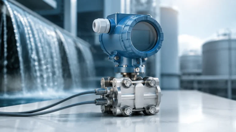
DP meters are among the most established technologies in gas flow metering. They operate on Bernoulli’s principle: as a gas passes through a constriction (like an orifice plate or Venturi tube), its velocity increases and its pressure decreases. The square root of the pressure difference between the upstream and downstream sides is proportional to the flow rate.
* Advantages: No moving parts, well-standardized, suitable for high temperatures and pressures.
* Limitations: Significant pressure drop, limited turndown ratio (typically 4:1), and high sensitivity to installation errors.
2. Thermal Mass Flow Meters
Thermal mass flow meters utilize the heat-conducting properties of the gas. They typically consist of two sensors: one that measures the ambient gas temperature and a second that is heated to a specific temperature above the ambient. As gas flows past the heated sensor, it carries away heat. The amount of energy required to maintain the temperature differential is directly proportional to the mass flow rate.
* Advantages: Direct mass measurement without P/T compensation, excellent low-flow sensitivity, and no moving parts.
* Limitations: Primarily used for clean gases; moisture or particulates can coat the sensors and cause drift.
3. Vortex Flow Meters
Vortex meters operate on the Karman Vortex Street principle. When a gas flows past a "shedder bar" placed in the stream, vortices are created on alternating sides. The frequency of these vortices is directly proportional to the gas velocity.
* Advantages: Wide turndown ratio, low maintenance, and suitable for steam and high-velocity gas applications.
* Limitations: Requires a minimum Reynolds number to function; not suitable for very low-flow applications.
4. Ultrasonic Flow Meters (Transit-Time)
Ultrasonic gas meters use sound waves to measure velocity. Two transducers send ultrasonic pulses back and forth across the pipe. The pulse traveling with the flow moves faster than the one traveling against it. The difference in transit time is proportional to the gas velocity.
* Advantages: Non-intrusive (no pressure drop), high accuracy, and capable of handling bidirectional flow.
* Limitations: Higher initial cost; performance can be affected by acoustic noise from valves or high-frequency vibrations.
Selection Criteria for Gas Flow Metering
Selecting the appropriate meter requires a detailed analysis of the application parameters. Engineers should evaluate the following criteria before procurement:
| Criteria | Differential Pressure | Thermal Mass | Vortex | Ultrasonic |
| :— | :— | :— | :— | :— |
| Accuracy | ±1% to ±3% | ±1% | ±1% | ±0.5% to ±1% |
| Turndown Ratio | 4:1 | 100:1 | 20:1 | 50:1 |
| Pressure Drop | High | Negligible | Medium | None |
| Moving Parts | No | No | No | No |
| Primary Use | General Purpose | Compressed Air/Pure Gas | Steam/High Velocity | Custody Transfer |
| Typical Cost | Low to Medium | Medium | Medium | High |
Gas Composition and Compatibility
The chemical properties of the gas are paramount. For corrosive gases like chlorine or hydrogen sulfide, wetted parts must be constructed from specialized alloys (e.g., Hastelloy or Monel). For explosive gases, the instrumentation must carry appropriate hazardous area certifications (ATEX, IECEx, or UL).
Process Conditions
* Temperature: High-temperature gases (above 250°C) may rule out certain ultrasonic or thermal mass sensors.
* Pressure: High-pressure applications require robust housing and may necessitate DP or vortex meters.
* Flow Range: If the application involves high variability (e.g., leak detection vs. full production), a high turndown ratio is required, favoring thermal mass or ultrasonic technologies.
Installation Considerations and Best Practices
Even the most accurate gas flow meter will fail to perform if installed incorrectly. Gas flow profiles are highly sensitive to disturbances in the piping.
Straight Pipe Runs
Most gas flow meters require a specific length of straight pipe upstream and downstream to ensure a fully developed, laminar flow profile. Obstructions like elbows, valves, and reducers create turbulence that can lead to significant measurement errors. As a general rule, 10 to 20 pipe diameters upstream and 5 diameters downstream are required, though this varies by technology.
Flow Conditioners
In installations where space is limited and required straight runs cannot be achieved, flow conditioners or straightening vanes can be used. These devices break up large-scale turbulence and force the gas into a stable profile before it reaches the sensor.
Moisture and Condensate
Wet gas is a common challenge in gas flow metering. If liquid droplets form in the gas stream, they can cause physical damage to turbine blades, interfere with ultrasonic signals, or create false readings in thermal sensors. Meters should be installed at high points in the piping, and drip legs or separators should be used to remove moisture upstream of the meter.
Common Risks and Limitations
Industrial gas flow metering is subject to several environmental and operational risks that can compromise data integrity:
1. Calibration Drift: Over time, sensors may drift due to contamination or electronic aging. Regular calibration against a traceable standard is necessary, especially for custody transfer applications.
2. Compressibility Factor (Z): For many gases, the ideal gas law (PV=nRT) is insufficient at high pressures. The compressibility factor (Z) must be calculated to account for non-ideal behavior, which requires specialized flow computers.
3. Pressure Drop Costs: Meters that create a high pressure drop (like orifice plates) increase the workload on compressors. Over the lifespan of a plant, the energy cost of this pressure drop can exceed the initial purchase price of a more expensive, low-pressure-drop meter like an ultrasonic or thermal mass unit.
4. Noise Interference: In ultrasonic metering, control valves located near the meter can generate ultrasonic noise that interferes with the transducers. Proper spacing and acoustic insulation are required.
Integration with Level Measurement
In B2B industrial automation, gas flow metering is rarely an isolated task. It is often part of a broader mass balance strategy. For example, in chemical reactors, the rate of gas injection must be precisely balanced with the liquid level and pressure inside the vessel. Utilizing reliable level sensors—such as radar or ultrasonic transmitters available from Welk—ensures that the gas flow data is contextualized within the overall process volume. This integration allows for more precise dosing, improved reaction yields, and enhanced safety protocols.
Frequently Asked Questions (FAQ)
Q: Why is gas flow metering more difficult than liquid flow metering?
A: Gas is highly compressible, meaning its volume changes with temperature and pressure. Liquids are generally incompressible. Gas measurement requires constant monitoring of P and T to calculate accurate mass or standardized volume.
Q: What is the difference between Nm³/h and m³/h?
A: m³/h (Actual Cubic Meters per Hour) measures the volume at the current operating conditions. Nm³/h (Normal Cubic Meters per Hour) refers to the volume the gas would occupy at standard conditions (typically 0°C and 1.013 bar).
Q: Can I use one meter for different types of gases?
A: It depends on the technology. Thermal mass meters are calibrated for specific gas thermal properties and must be recalibrated if the gas composition changes. Vortex and DP meters are more flexible but still require density adjustments for different gases.
Q: How often should gas flow meters be calibrated?
A: For critical custody transfer, annual calibration is standard. For process monitoring, every 2 to 3 years may be sufficient, provided there is no evidence of drift or sensor fouling.
Conclusion
Gas flow metering is a fundamental pillar of modern industrial engineering. By understanding the physical principles of gas behavior and the technical strengths of various metering technologies, organizations can select systems that provide long-term reliability and accuracy. Whether managing compressed air for a factory or high-pressure natural gas for a power plant, the integration of precise flow data with robust level measurement solutions remains the gold standard for process optimization. For further technical specifications on industrial measurement instruments, visiting the Main Page offers access to a wide range of solutions tailored for demanding industrial environments.