Gauge Water Level
Gauge Water Level
In industrial automation and process control, the ability to accurately gauge water level is fundamental to operational safety, inventory management, and environmental compliance. From municipal water treatment facilities to complex chemical processing plants, selecting the appropriate measurement technology requires a deep understanding of physical principles, environmental constraints, and specific application requirements. This guide serves as a technical reference for engineers and plant managers to evaluate the most effective methods to gauge water level in diverse industrial environments.
Core Measurement Principles
To effectively gauge water level, several physical principles are utilized, each offering distinct advantages depending on the medium's characteristics and the vessel's geometry. The most common technologies include radar, ultrasonic, hydrostatic, and magnetic measurement.
Radar Level Measurement (Non-Contact)
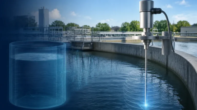
Radar level meters operate on the Time-of-Flight (ToF) principle. The device emits high-frequency electromagnetic waves (typically in the 26GHz or 80GHz range) toward the water surface. These waves are reflected back to the sensor. By measuring the time interval between emission and reception, the instrument calculates the distance to the water surface.
* FMCW (Frequency Modulated Continuous Wave): Modern 80GHz radar units often use FMCW technology, which provides superior resolution and accuracy by measuring frequency shifts rather than just time pulses. This is particularly effective in narrow tanks or where internal obstructions are present.
* Advantages: Radar is unaffected by temperature fluctuations, pressure changes, or the presence of dust and vapors. It is the gold standard for high-precision applications.
Ultrasonic Level Measurement (Non-Contact)
Similar to radar, ultrasonic sensors use the ToF principle but utilize sound waves instead of electromagnetic waves. The sensor emits an ultrasonic pulse that bounces off the water surface and returns to the transducer.
* Speed of Sound Considerations: Because the speed of sound is influenced by air temperature, most ultrasonic gauges include integrated temperature compensation. However, they can be affected by heavy foam, wind, or significant temperature gradients in the vapor space.
* Best Use Case: Ultrasonic sensors are highly cost-effective for open-channel flow measurement and standard atmospheric water tanks.
Hydrostatic Pressure Measurement (Contact)
Hydrostatic level transmitters gauge water level by measuring the pressure exerted by the liquid column at a specific point. The relationship is defined by the formula: *P = ρgh*, where *P* is pressure, *ρ* (rho) is the density of the liquid, *g* is gravity, and *h* is the height of the liquid.
* Submersible Transmitters: These are lowered into the water, with a vented cable to compensate for atmospheric pressure changes.
* External Mounting: In pressurized tanks, a differential pressure (DP) transmitter is used to subtract the head pressure from the total pressure to isolate the liquid level.
Magnetic Level Gauges (Visual and Contact)
These instruments utilize a float containing a permanent magnet. As the float moves with the water level in a bypass chamber, it flips magnetic flaps or actuates a reed switch transmitter. This provides both a local visual indication and a remote electronic signal.
Technology Selection Matrix
Choosing the right instrument to gauge water level depends on the specific parameters of the installation. The following table provides a comparison of common technologies.
| Technology | Typical Accuracy | Maximum Range | Process Temperature | Key Advantage |
| :— | :— | :— | :— | :— |
| 80GHz Radar | ±2 mm | 120 m (393 ft) | -40°C to 200°C | Highest precision; ignores steam/vapor |
| Ultrasonic | ±0.25% of range | 30 m (98 ft) | -40°C to 80°C | Cost-effective; non-contact |
| Hydrostatic | ±0.1% to 0.5% | 500 m (1640 ft) | -10°C to 80°C | Ideal for deep wells and boreholes |
| Magnetic Gauge | ±5 mm | 6 m (20 ft) | Up to 400°C | Visual indication without power |
Critical Installation Considerations
Correct installation is as vital as selecting the right technology. Failure to account for physical constraints can lead to "ghost echoes" or signal loss.
1. The Dead Zone (Blocking Distance): Both radar and ultrasonic sensors have a minimum distance near the sensor face where measurements cannot be taken. For ultrasonic sensors, this is typically 0.25m to 0.6m (0.8ft to 2ft). Ensure the maximum water level does not enter this zone.
2. Beam Angle and Obstructions: Sensors emit signals in a cone shape. If this beam hits tank walls, ladders, or agitators, it can cause false readings. 80GHz radar offers a much narrower beam (often as small as 3 degrees) compared to ultrasonic sensors (typically 10-12 degrees), allowing for easier installation in cramped spaces.
3. Stilling Wells: In applications with high turbulence or surface foam, installing the sensor inside a stilling well (a vertical pipe) can provide a calm surface for accurate measurement. This is common in reservoir management and chemical mixing tanks.
4. Mounting Position: Sensors should generally be mounted at least 200mm (8 inches) away from the tank wall to avoid signal interference. For hydrostatic sensors, avoid placement near inlets where high-velocity water flow could create localized pressure fluctuations.
Limitations and Environmental Risks
While modern instruments are robust, certain conditions can compromise the ability to gauge water level accurately:
* Heavy Foam: Foam can absorb ultrasonic signals, leading to a "lost echo" error. Radar is generally more resistant but may still experience signal attenuation with very thick, dense foam.
* Vacuum and Pressure: Ultrasonic sensors cannot operate in a vacuum because sound waves require a medium (air) to travel. Radar, being electromagnetic, functions perfectly in a vacuum.
* Chemical Compatibility: For hydrostatic and magnetic gauges, the wetted materials (316L stainless steel, PTFE, etc.) must be compatible with the liquid. In wastewater applications, buildup on the sensor face can also affect hydrostatic accuracy.
* Rapid Temperature Changes: Sudden shifts in temperature can cause condensation on the sensor face. While many radar units feature "drip-off" antenna designs to mitigate this, ultrasonic sensors may require a heated face or protective shielding.

Practical Maintenance and Calibration
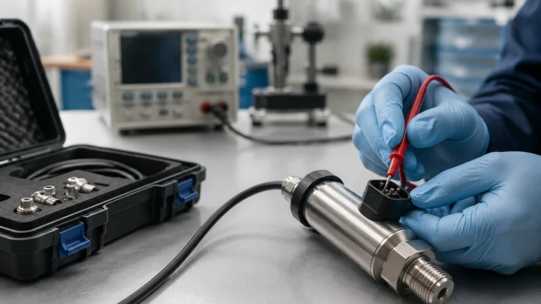
To maintain the integrity of water level data, a routine maintenance schedule should be implemented. For non-contact sensors, this involves checking the transducer face for buildup or condensation. For hydrostatic sensors, the vent tube in the cable must be checked for blockages, as a clogged vent will cause errors during changes in atmospheric pressure.
Calibration should be verified annually or according to local regulatory requirements. This is typically done using a "dry calibration" (configuring the electronics based on tank dimensions) followed by a "wet calibration" (comparing the sensor reading against a manual dip tape or a known reference point).
Frequently Asked Questions (FAQ)
Q: Can I use an ultrasonic sensor to gauge water level in a boiling tank?
A: It is not recommended. Steam and heavy vapor significantly change the speed of sound, leading to large errors. Additionally, condensation on the transducer face can block the signal. Radar is the preferred choice for such environments.
Q: How does water density affect hydrostatic level measurement?
A: Hydrostatic sensors measure pressure, not height directly. If the water density changes (e.g., due to high salinity or temperature shifts), the pressure at the bottom will change even if the level remains constant. The transmitter must be calibrated for the specific gravity of the fluid.
Q: What is the benefit of 80GHz radar over 26GHz radar?
A: The 80GHz frequency allows for a smaller antenna and a much narrower beam angle. This makes it easier to avoid internal tank obstructions and provides better performance in vessels with complex geometries.
Conclusion
Selecting the right system to gauge water level requires balancing technical requirements with budget constraints. For high-precision chemical or high-temperature applications, radar remains the most reliable choice. For general water management and wastewater applications, ultrasonic and hydrostatic sensors offer excellent reliability and value.
For engineers seeking detailed product specifications or customized OEM/ODM solutions, it is recommended to Review product options and application support on the Welk Main Page to find the specific instrument that meets your project's environmental and accuracy demands.