Gauging Liquid
Gauging Liquid
In industrial process control, gauging liquid refers to the precise measurement of the level, volume, or mass of a fluid within a storage tank or process vessel. Accurate liquid gauging is fundamental to inventory management, overfill prevention, and ensuring the efficiency of automated systems. Whether the application involves corrosive chemicals, volatile hydrocarbons, or municipal water, selecting the correct instrumentation requires a deep understanding of the physical principles governing measurement and the environmental factors that can influence sensor performance.
For engineers and plant managers, the process of gauging liquid is not a one-size-fits-all task. It involves balancing the need for accuracy against installation constraints, maintenance requirements, and budget. This guide examines the primary technologies used in modern industrial level measurement, their operating principles, and the criteria for selecting the most effective solution.
Measurement Principles for Gauging Liquid
To effectively monitor industrial fluids, several physical principles are utilized. These range from measuring the time it takes for a wave to reflect off a surface to sensing the pressure exerted by a liquid column.
Radar Level Measurement (Time of Flight)
Radar technology, specifically non-contacting radar and Guided Wave Radar (GWR), is a leading method for gauging liquid in challenging environments.
* Non-contact Radar: These devices emit high-frequency electromagnetic pulses (typically in the 26 GHz or 80 GHz range). The pulses travel to the liquid surface and are reflected back to the sensor. The distance is calculated based on the "Time of Flight" (ToF). Because electromagnetic waves do not require a medium for travel, radar is unaffected by vacuum, temperature fluctuations, or high pressure.
* Guided Wave Radar (GWR): GWR uses a probe (rod or cable) to guide the microwave pulse directly to the liquid surface. This method is highly effective for liquids with low dielectric constants or in tanks with heavy foam or turbulence, as the probe concentrates the signal energy.
Ultrasonic Level Measurement
Ultrasonic sensors function similarly to radar but use sound waves instead of electromagnetic pulses. The sensor emits a high-frequency sound pulse that reflects off the liquid surface. The time taken for the echo to return is proportional to the distance. While cost-effective, ultrasonic gauging is sensitive to air temperature (which affects sound speed) and can be hindered by heavy dust, vapor, or foam that absorbs the sound energy.
Hydrostatic Pressure Measurement
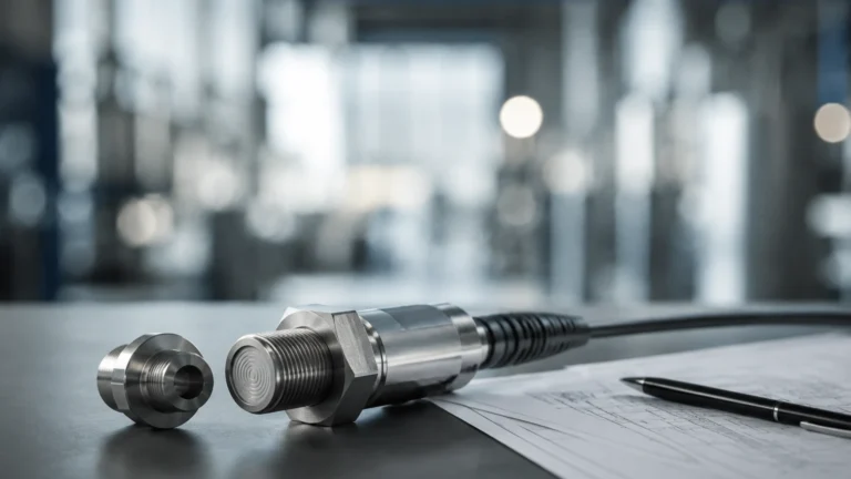
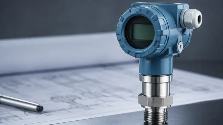
Hydrostatic gauging relies on the principle that the pressure at the bottom of a vessel is directly proportional to the height of the liquid column above it, multiplied by the liquid's density and gravity ($P = \rho gh$). A pressure transmitter installed at the base of the tank (or submerged) converts this mechanical pressure into an electrical signal. This method is robust and widely used in vented tanks where the liquid density remains relatively constant.
Magnetic Level Gauges
Magnetic gauging liquid systems use a float containing an internal magnet that moves with the liquid level. This float is housed within a bypass chamber connected to the tank. Outside the chamber, a series of magnetic flags or a magnetic transmitter tracks the float's position. This provides a clear visual indication without the liquid coming into contact with the viewing glass, making it ideal for high-pressure or toxic applications.
Technology Selection Matrix
Choosing the right instrument for gauging liquid depends on the specific process conditions. The following table provides a comparison of common technologies.
| Technology | Accuracy | Media Compatibility | Max Temperature | Max Pressure | Best Use Case |
| :— | :— | :— | :— | :— | :— |
| Non-Contact Radar | ±1 mm to ±5 mm | Corrosive, viscous, clean | Up to 450°C (842°F) | Up to 160 bar (2320 psi) | Bulk storage, reactors |
| Guided Wave Radar | ±2 mm to ±5 mm | Low dielectric, foam | Up to 400°C (752°F) | Up to 400 bar (5800 psi) | Small tanks, interfaces |
| Ultrasonic | ±0.25% of range | Water-based, acids | Up to 80°C (176°F) | Up to 3 bar (43.5 psi) | Water treatment, open sumps |
| Hydrostatic | ±0.1% to ±0.5% | Slurries, oils, water | Up to 120°C (248°F) | Varies by sensor | Vented tanks, deep wells |
| Magnetic Gauge | ±5 mm to ±10 mm | High pressure, toxic | Up to 400°C (752°F) | Up to 250 bar (3625 psi) | Boiler drums, oil/gas |
Key Evaluation Criteria for Gauging Liquid
Before selecting a device for gauging liquid, engineers must evaluate the following four factors to ensure long-term reliability.
1. Fluid Properties
* Dielectric Constant (εr): For radar measurement, the dielectric constant of the liquid determines how much signal is reflected. Water has a high εr (~80), making it easy to measure, while hydrocarbons like oil have a low εr (~2), requiring more sensitive radar units.
* Viscosity and Coating: Highly viscous liquids or those that crystallize can coat probes (in GWR) or clog pressure diaphragms. In these cases, non-contact radar or flush-diaphragm hydrostatic transmitters are preferred.
* Chemical Compatibility: The wetted parts of the sensor (stainless steel, PTFE, Hastelloy) must be compatible with the liquid to prevent corrosion.
2. Process Conditions
* Turbulence and Foam: Surface agitation can scatter radar and ultrasonic signals. Foam can act as an insulator, absorbing signals. GWR or hydrostatic sensors are often better suited for these conditions.
* Vapor and Condensation: In closed tanks, the space above the liquid may contain vapors. While radar passes through vapor easily, ultrasonic waves may be distorted. Condensation on the sensor face can also interfere with non-contact measurements.
3. Tank Geometry
Internal structures like agitators, heating coils, or ladders can create false echoes for radar and ultrasonic sensors. Modern sensors use "false echo suppression" software to map out these obstructions, but proper placement remains critical.
4. Accuracy Requirements
For custody transfer (where liquid is being bought or sold), high-precision radar with ±1 mm (0.04 in) accuracy is required. For simple pump control or high-level alarms, a standard ultrasonic sensor or level switch may suffice.
Installation Considerations
Proper installation is as important as selecting the right technology. When gauging liquid, follow these engineering best practices:
* Nozzle Design: For non-contact radar, the nozzle height should be kept to a minimum to prevent signal interference. The diameter of the nozzle should be large enough to allow the signal beam to expand without hitting the nozzle walls.
* Dead Zones (Blocking Distance): Every top-mounted sensor has a "dead zone" directly beneath the sensor where it cannot measure. Ensure the maximum liquid level does not enter this zone, or the sensor will provide an error or a fixed reading.
* Positioning: Avoid mounting sensors in the center of a tank (where multiple reflections can occur) or too close to the tank wall. Typically, the sensor should be placed 1/6th to 1/4th of the tank diameter away from the wall.
* Hydrostatic Venting: If using a submersible hydrostatic sensor, the reference capillary tube in the cable must be vented to the atmosphere and protected from moisture to ensure accurate gauge pressure readings.

Common Risks and Limitations
Despite advancements in technology, gauging liquid remains subject to environmental challenges:
1. Density Variations: Hydrostatic sensors are calibrated based on a specific liquid density. If the temperature changes significantly or the liquid composition varies, the density changes, leading to measurement errors. In these cases, radar is a superior choice as it is density-independent.
2. Vacuum Conditions: Ultrasonic sensors cannot function in a vacuum because sound waves require a medium (air/gas) to travel. Radar is the standard for vacuum applications.
3. Signal Absorption: Heavy steam or thick dust can attenuate signals. Using higher-power 80 GHz radar or GWR can mitigate these issues by focusing the signal energy.
Engineering Checklist Before Procurement
When preparing to specify a system for gauging liquid, confirm the following data points with your supplier:
* Liquid Name and Concentration: (e.g., 98% Sulfuric Acid).
* Operating Temperature and Pressure: Both normal and maximum possible values.
* Tank Dimensions: Total height, diameter, and shape (flat, conical, or dished bottom).
* Process Connection: Flange size, thread type, or sanitary fitting.
* Output Signal: 4-20mA HART, RS485 Modbus, or wireless protocols.
For a comprehensive range of industrial measurement tools, including radar, ultrasonic, and magnetic solutions, you can Main Page to review product options and application support from Welk.
Frequently Asked Questions (FAQ)
Q: Can I use one sensor for two different liquids in the same tank?
A: If the liquids are miscible (mixed), you measure the total level. If they are immiscible (e.g., oil on water), you need a Guided Wave Radar (GWR) capable of interface measurement to detect both the top level and the boundary between the two liquids.
Q: How often do liquid gauging sensors need calibration?
A: This depends on the technology. Radar and ultrasonic sensors are generally very stable. Hydrostatic sensors may require annual zero-point checks to account for sensor drift. In critical safety applications, proof testing should be performed according to SIL (Safety Integrity Level) requirements.
Q: What is the advantage of 80 GHz radar over 26 GHz radar?
A: 80 GHz radar has a much narrower beam angle. This allows it to be installed in smaller nozzles, avoid internal tank obstructions more easily, and provide better accuracy in small vessels or when gauging liquid with low dielectric properties.
By understanding these technical nuances, industrial operators can ensure that their liquid gauging systems provide the reliable data necessary for safe and efficient plant operations.