Gauss Meter Calibration
Gauss Meter Calibration
In industrial environments where magnetic level measurement is a critical component of process control, the accuracy of magnetic field measurement is paramount. Magnetic level gauges, switches, and transmitters rely on the precise interaction between magnetic floats and external sensing elements. To ensure these systems function correctly, engineers and technicians utilize Gauss meters (also known as magnetometers) to verify magnetic field strength. However, the reliability of these measurements is entirely dependent on rigorous gauss meter calibration. This article explores the technical principles, calibration methodologies, and practical considerations for maintaining Gauss meters in industrial B2B applications.
Understanding the Principles of Magnetic Field Measurement
Before detailing the calibration process, it is essential to understand how a Gauss meter operates. Most modern industrial Gauss meters utilize the Hall Effect to detect and measure magnetic flux density.
The Hall Effect Principle
When a thin, flat conductor or semiconductor (a Hall element) carries an electric current and is placed in a magnetic field perpendicular to the direction of the current, a voltage is generated across the conductor. This voltage, known as the Hall voltage ($V_H$), is directly proportional to the strength of the magnetic field ($B$). The relationship is defined by the formula:
$$V_H = R_H \cdot \left(\frac{I \cdot B}{d}\right)$$
Where:
* $V_H$ is the Hall voltage.
* $R_H$ is the Hall coefficient.
* $I$ is the current flowing through the conductor.
* $B$ is the magnetic flux density.
* $d$ is the thickness of the conductor.
Units of Measurement
In the International System of Units (SI), magnetic flux density is measured in Tesla (T). However, in many industrial contexts, the CGS unit, Gauss (G), remains the standard. The conversion is straightforward: $1\text{ Tesla} = 10,000\text{ Gauss}$. For industrial level measurement, technicians often work in the range of $0.1\text{ mT}$ (1 Gauss) to several Tesla, depending on the strength of the permanent magnets used in the floats of magnetic level gauges.
The Role of Gauss Meters in Industrial Level Measurement
For a professional manufacturer like Welk, Gauss meters are indispensable tools for quality control and field diagnostics. Magnetic level gauges (MLGs) operate on the principle of magnetic coupling. A float containing a high-strength permanent magnet rises and falls with the liquid level inside a bypass chamber. This float’s magnetic field must be strong enough to penetrate the chamber wall and actuate an external indicator or transmitter.
Gauss meter calibration ensures that the instruments used to test these floats are providing accurate data. If a Gauss meter is out of calibration, a technician might incorrectly conclude that a float magnet has lost its strength (demagnetized) or, conversely, fail to detect a magnet that is too weak to operate the gauge reliably at high temperatures. In industries such as chemical processing or oil and gas, where tank levels must be monitored with high precision, an uncalibrated meter can lead to process inefficiencies or safety risks.
For comprehensive information on the full range of level measurement technologies, including radar and ultrasonic solutions, you may refer to the Main Page.
Gauss Meter Calibration Procedures and Standards
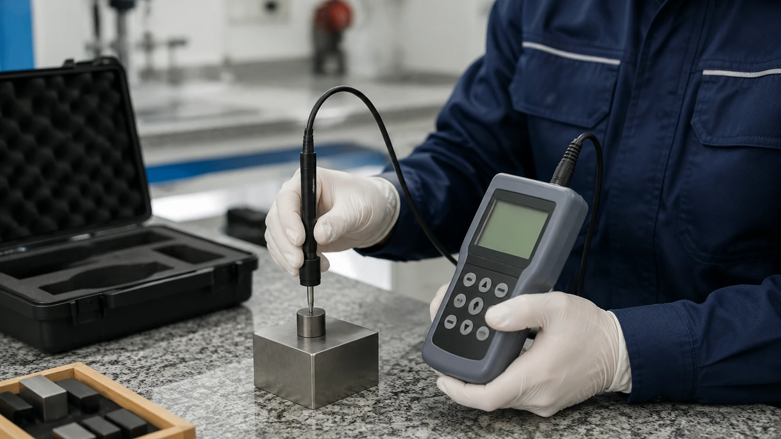
Calibration is the process of comparing the readings of a device under test (DUT) against a known reference standard. For Gauss meters, this typically involves two primary steps: zero-point adjustment and span verification using a reference magnetic field.
1. Zero-Point Calibration
The first step is to eliminate the influence of the Earth's magnetic field and any ambient electromagnetic interference (EMI). This is achieved using a "Zero Gauss Chamber." This chamber is a high-permeability Mu-metal cylinder that shields the probe from external magnetic fields. The probe is inserted into the chamber, and the meter is adjusted until it reads exactly zero.
2. Reference Field Verification (Helmholtz Coils)
To verify the span or sensitivity, the probe is placed into a known, stable magnetic field. This is often generated by a Helmholtz coil. A Helmholtz coil consists of two identical circular magnetic coils placed on a common axis. When current flows through them, they produce a highly uniform magnetic field in the center of the space between the coils. Because the field strength is directly proportional to the current and the number of turns in the wire, it serves as a primary standard for calibration.
3. Reference Magnets
For field service and quick checks, certified reference magnets are used. These are permanent magnets (often Neodymium or Samarium Cobalt) that have been measured by a laboratory with NIST-traceable equipment. They provide a fixed point (e.g., 1000 Gauss) to verify the meter's accuracy across its operating range.
Selection Criteria for Calibration Equipment and Services
When selecting a Gauss meter or a calibration service, industrial users must evaluate the technical specifications against their specific application requirements. The following table provides a guideline for evaluating Gauss meter performance in industrial level measurement contexts.
| Feature | Requirement for Level Measurement | Importance |
| :— | :— | :— |
| Accuracy | ±0.5% to ±2% of reading | High – Ensures float magnet integrity. |
| Frequency Range | DC (Static) to 10 kHz | Medium – Most level magnets are static (DC). |
| Probe Type | Transverse and Axial | High – Depends on float geometry. |
| Temperature Compensation | Required | High – Industrial tanks often operate at high temps. |
| Traceability | NIST or equivalent | High – Mandatory for ISO 9001 compliance. |
| Measurement Range | 0.1 G to 20,000 G | Medium – Covers all standard level floats. |
Transverse vs. Axial Probes
* Transverse Probes: The Hall element is oriented to measure magnetic fields perpendicular to the probe's flat surface. These are ideal for measuring the surface of a cylindrical float magnet.
* Axial Probes: The Hall element is at the tip, measuring fields parallel to the probe's length. These are used for measuring the field inside a tube or at the end of a magnetic rod.
Installation and Environmental Considerations
Effective gauss meter calibration is not just about the instrument; it is about how the measurement is conducted in the field. Several environmental factors can degrade the accuracy of magnetic measurements.
Temperature Drift
Hall effect sensors are inherently sensitive to temperature changes. As the temperature rises, the mobility of the charge carriers in the semiconductor changes, leading to drift in the Hall voltage. High-quality Gauss meters include internal thermistors to provide active temperature compensation. When performing field checks on magnetic level gauges installed on high-temperature boilers, the technician must allow the probe to reach thermal equilibrium or use a probe rated for high-temperature exposure.
Proximity to Ferrous Materials
The presence of steel structures, pipes, or tools can distort the magnetic field lines being measured. This is known as the "shunting effect." When calibrating or using a Gauss meter near a tank, ensure that the probe is not in immediate proximity to ferrous materials that could redirect the flux away from the sensor.
Probe Orientation and Placement
The Hall voltage is dependent on the sine of the angle between the magnetic field vector and the sensor plane. A misalignment of only 5 degrees can result in a measurement error of approximately 0.4%. Significant misalignment can lead to much larger errors. During calibration, the probe must be held in a fixed jig to ensure perfectly perpendicular alignment with the reference field.
Common Risks and Limitations in Magnetic Calibration
While gauss meter calibration is a robust process, there are limitations that engineers must acknowledge to avoid false readings.
1. Non-Linearity: No Hall sensor is perfectly linear across its entire range. A meter calibrated at 1000 Gauss may show higher error percentages at 10,000 Gauss. It is critical to calibrate the meter at a point close to the expected measurement value.
2. Probe Fragility: The Hall element is typically a very thin ceramic or semiconductor flake. Dropping the probe or applying excessive pressure can cause micro-fractures that result in erratic readings or permanent drift. Always inspect the probe for physical damage before calibration.
3. Saturation: If the magnetic field exceeds the meter's rated range, the sensor will saturate, providing a constant maximum output regardless of further increases in field strength. This can be dangerous if a technician assumes the field is lower than it actually is.
4. Battery Levels: In handheld units, low battery voltage can affect the constant current source supplied to the Hall element, leading to inaccurate voltage output. Always calibrate with a fully charged battery or a stable external power supply.
Frequently Asked Questions (FAQs)
Q: How often should a Gauss meter be calibrated?
A: For most industrial B2B applications, an annual (12-month) calibration cycle is standard. However, if the meter is used in harsh environments, subjected to mechanical shock, or used for critical safety inspections, a 6-month cycle is recommended.
Q: Can I perform gauss meter calibration in-house?
A: You can perform "verification" in-house using certified reference magnets. However, true "calibration" that meets ISO/IEC 17025 standards usually requires a controlled laboratory environment with Helmholtz coils and precise current sources.
Q: What is the difference between a Gauss meter and a Tesla meter?
A: There is no functional difference; they are the same instrument. The name simply refers to the unit of measure the device displays (Gauss vs. Tesla).
Q: Why does my Gauss meter read a value even when no magnet is nearby?
A: This is likely due to the Earth's magnetic field (approximately 0.5 Gauss) or nearby electronic equipment. You must use a Zero Gauss Chamber to properly zero the instrument before taking sensitive measurements.
Q: Does the material of the probe affect the calibration?
A: The probe housing is usually non-magnetic (plastic or brass) to avoid interfering with the field. If the housing becomes contaminated with iron filings or magnetic dust, it will significantly bias the calibration and must be cleaned.
In conclusion, gauss meter calibration is a fundamental requirement for the maintenance of magnetic level measurement systems. By understanding the Hall Effect, following standardized calibration procedures, and accounting for environmental variables, industrial operators can ensure that their Welk level instruments and associated diagnostic tools provide the accuracy required for modern industrial automation. For further technical specifications and product support, visit the Main Page.