H20 Line
H20 Line
In industrial level measurement, the term "H20 line" refers to the critical interface between water (H2O) and the atmosphere or gas phase within a vessel, tank, or open channel. Monitoring this line accurately is fundamental to process control, safety, and inventory management across various sectors, including water treatment, chemical processing, and power generation. Whether the application involves a municipal reservoir, a cooling tower basin, or a high-pressure boiler, the technology chosen to track the H20 line must account for the physical properties of water, environmental conditions, and the specific geometry of the containment system.
Establishing a reliable H20 line measurement requires an understanding of the diverse technologies available. From non-contact methods like radar and ultrasonic sensors to contact-based solutions like hydrostatic transmitters and magnetic level gauges, each technology offers specific advantages depending on the turbulence, temperature, and pressure of the water being monitored. For engineers seeking comprehensive instrumentation options, visiting the Main Page provides a starting point for exploring the full range of industrial level measurement solutions.
Measurement Principles for H20 Line Detection
To effectively monitor the H20 line, engineers must first understand the physics behind the measurement. Water level detection generally falls into two categories: contact and non-contact measurement.
Hydrostatic Pressure Measurement
Hydrostatic level measurement is based on the principle that the pressure at a specific point in a static liquid is proportional to the height of the liquid column above it. The formula used is $P = \rho \times g \times h$, where $P$ is pressure, $\rho$ (rho) is the density of water, $g$ is gravity, and $h$ is the height of the water.
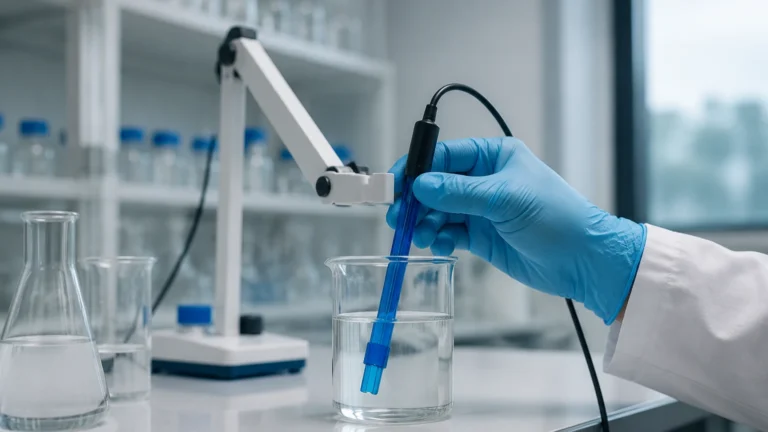
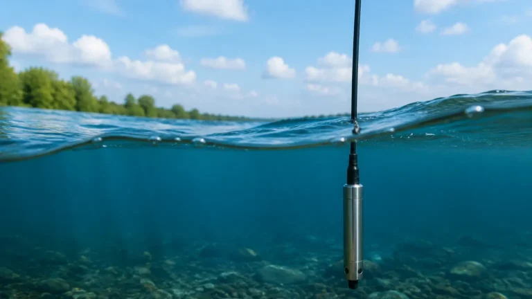
In a typical H20 line application, a submersible transmitter or a flange-mounted pressure sensor is placed at the bottom of the tank. As the H20 line rises, the pressure on the diaphragm increases. This method is highly reliable for vented tanks where the atmospheric pressure is constant. For pressurized vessels, a differential pressure (DP) transmitter is required to subtract the headspace pressure from the total bottom pressure.
Ultrasonic (Time-of-Flight)
Ultrasonic sensors are non-contact devices that emit high-frequency sound waves toward the H20 line. These waves reflect off the water surface and return to the sensor. The device calculates the distance based on the time it takes for the pulse to travel to the surface and back. This technology is cost-effective and ideal for open-air applications like flumes or basins. However, it is sensitive to air temperature fluctuations and surface foam, which can absorb or scatter the sound waves.
Radar Level Measurement
Radar technology, particularly Frequency Modulated Continuous Wave (FMCW) radar, is often considered the gold standard for H20 line tracking. Operating at frequencies such as 26GHz or 80GHz, radar sensors emit electromagnetic pulses that reflect off the water surface. Unlike ultrasonic waves, radar signals are unaffected by temperature shifts, vacuum, or high pressure. The high dielectric constant of water (approximately 80) makes it an excellent reflector for radar signals, ensuring a strong return signal even in the presence of steam or dust.
Magnetic Level Gauges
Magnetic level gauges provide both a visual indication and an electronic signal. A float containing a permanent magnet moves along a bypass chamber connected to the vessel. As the H20 line moves, the float moves with it, flipping magnetic flags on an external scale and actuating reed switches or a magnetostrictive transmitter for remote monitoring. This is a robust solution for high-pressure H20 lines in boiler applications.
Technical Selection Criteria for H20 Line Instrumentation
Selecting the correct instrument for an H20 line application requires a detailed analysis of the process environment. The following table outlines the primary considerations for the most common technologies.
| Technology | Best Use Case | Accuracy | Limitations |
| :— | :— | :— | :— |
| Radar (80GHz) | Narrow tanks, turbulent surfaces, steam | ±1 mm (0.04 in) | Higher initial cost |
| Ultrasonic | Open channels, wastewater basins | ±0.25% of range | Affected by foam and wind |
| Hydrostatic | Deep wells, vented storage tanks | ±0.1% to 0.5% | Sensitive to density changes |
| Magnetic Gauge | High-pressure boilers, visual bypass | ±5 mm (0.2 in) | Moving parts; requires bypass piping |
| Level Switch | Overfill protection, pump control | N/A (Point level) | No continuous measurement |
Environmental Factors
When the H20 line is located outdoors, such as in a dam or reservoir, the sensor must be rated for extreme weather. For indoor industrial tanks, chemical compatibility is paramount. While pure water is non-corrosive, the presence of additives, acids, or salts in the H20 line requires the use of specialized materials like PVDF, PTFE, or 316L stainless steel for wetted parts.
Installation Considerations for the H20 Line
Correct installation is as critical as sensor selection. An improperly mounted sensor will provide erratic data, even if the technology is theoretically perfect for the application.
1. Avoid Obstructions: For radar and ultrasonic sensors, the signal beam must have a clear path to the H20 line. Internal tank structures like ladders, agitators, or heating coils can create "false echoes." Advanced sensors allow for "false signal suppression," but physical clearance is always preferred.
2. Stilling Wells: In applications where the H20 line is highly turbulent—such as in a mixing tank—a stilling well (a vertical pipe with vent holes) can be used. This provides a calm surface for the sensor to measure, effectively filtering out the noise caused by waves.
3. Dead Zones: Every non-contact sensor has a "dead zone" or "blocking distance" directly beneath the sensor face where measurement is impossible. Ensure the sensor is mounted high enough so that the maximum H20 line never enters this zone.
4. Submersible Positioning: For hydrostatic sensors, the transmitter should not be placed directly in the path of an inlet flow, as the kinetic energy of the moving water can cause pressure spikes (velocity head error), leading to inaccurate H20 line readings.
Limitations and Common Risks
While water is generally a "friendly" medium for level measurement, certain conditions can challenge the accuracy of an H20 line reading.
* Foam Accumulation: In wastewater treatment, biological activity can create thick foam on the H20 line. Ultrasonic sensors may fail completely in these conditions, while low-frequency radar might penetrate the foam but lose signal strength. High-frequency 80GHz radar is typically the best solution for foamy H20 lines.
* Vapor and Condensation: In hot water tanks, condensation can form on the sensor face. While many modern radar sensors feature drip-off lens designs, excessive buildup can still attenuate the signal. Hydrostatic or magnetic gauges are often preferred in high-steam environments.
* Density Variations: Hydrostatic sensors assume a constant water density. If the water temperature changes significantly (e.g., from 4°C to 90°C), the density decreases, and the H20 line will appear lower to a pressure sensor than it actually is. Temperature compensation is required for high-precision hydrostatic measurement.
H20 Line Maintenance and Calibration
To ensure long-term reliability, a routine maintenance schedule should be implemented. For contact-based sensors like hydrostatic transmitters, periodic cleaning of the diaphragm is necessary to prevent the buildup of silt or scale. For non-contact sensors, the focus should be on ensuring the antenna or transducer face remains free of debris.
Calibration should be performed annually or according to regulatory requirements. This typically involves a "wet calibration" where the tank is filled to known points, or a "dry calibration" using a signal simulator or by measuring the distance to a fixed reference point. Modern digital instruments often support HART or Modbus protocols, allowing for remote diagnostics and calibration verification without removing the sensor from the process.
Frequently Asked Questions (FAQ)
Q: Can I use an ultrasonic sensor for a boiling H20 line?
A: It is not recommended. The high temperature changes the speed of sound in the air gap, and the heavy steam can scatter the ultrasonic pulses. Radar or hydrostatic sensors are much more reliable for boiling water.
Q: How does the H20 line measurement differ in a vacuum?
A: In a vacuum, ultrasonic sensors cannot function because sound waves require a medium (air) to travel. Radar sensors are unaffected by vacuum and are the ideal choice for vacuum degassers or similar equipment.
Q: What is the best way to measure the H20 line in a very deep well (over 100 meters)?
A: Submersible hydrostatic pressure transmitters are the standard for deep wells. They are lowered on a reinforced cable that contains a vent tube to compensate for changes in atmospheric pressure.
Q: Is 80GHz radar always better than 26GHz for water?
A: Not necessarily. While 80GHz offers a narrower beam and better resolution, 26GHz radar is often more than sufficient for large water storage tanks and can be more cost-effective. The choice depends on the tank's internal complexity and the required precision.
By carefully evaluating the physical environment and the specific requirements of the H20 line, engineers can select a measurement strategy that minimizes maintenance and maximizes process uptime. For those looking to compare specific hardware models or request technical support for a custom application, the Main Page offers a gateway to professional-grade level measurement instrumentation.