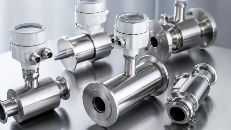
Vega Radars
Vega Radars
In the landscape of industrial automation and process control, radar level measurement has emerged as the gold standard for non-contact sensing. Among the most recognized names in this field are Vega radars, specifically the VEGAPULS series, which have set benchmarks for accuracy and reliability in challenging environments. For engineers and procurement specialists, understanding the nuances of radar technology—ranging from frequency selection to antenna design—is essential for optimizing process efficiency and safety.
Radar level meters operate on the principle of electromagnetic wave propagation. Unlike ultrasonic sensors, which rely on sound waves and are susceptible to air temperature fluctuations and vacuum conditions, radar signals travel at the speed of light and are largely unaffected by the vapor space composition. This makes them ideal for the diverse requirements of the water treatment, chemical, and oil and gas industries.
Understanding Radar Level Measurement Principles
Before selecting a specific instrument, it is critical to understand how radar technology interacts with the process media. Industrial radars generally utilize two primary methods for distance measurement: Time of Flight (ToF) and Frequency Modulated Continuous Wave (FMCW).
Time of Flight (ToF) / Pulse Radar
In pulse radar systems, the instrument emits a short microwave pulse toward the product surface. The pulse is reflected by the medium and received by the antenna. The instrument measures the time elapsed between emission and reception. Since the speed of light is constant, the distance is calculated as:
*Distance = (Speed of Light × Time) / 2*.
Frequency Modulated Continuous Wave (FMCW)
Modern high-end Vega radars often utilize FMCW technology. Instead of short pulses, the device emits a continuous signal with a constantly changing frequency. The reflected signal is received with a frequency shift compared to the signal being emitted at that exact moment. The frequency difference is directly proportional to the distance. FMCW provides a significantly higher signal-to-noise ratio, making it superior for measuring liquids with low dielectric constants or solids that create heavy dust.
The Role of the Dielectric Constant (εr)
The reflectivity of the radar signal depends heavily on the dielectric constant of the medium. Materials with high dielectric constants, such as water (εr ≈ 80), reflect signals strongly. In contrast, hydrocarbons and certain solvents have low dielectric constants (εr < 2), which absorb more energy and return a weaker signal. Choosing the right radar frequency and antenna type is vital when dealing with these "low-reflection" materials.
Key Series and Applications of Vega Radars
Vega radars are categorized primarily by their frequency and the nature of the media they are designed to measure. The transition from older 26 GHz technology to modern 80 GHz technology has redefined the capabilities of these sensors.
* VEGAPULS 60 Series: This legacy series includes versatile sensors like the VEGAPULS 61, 62, and 64. The 64 model, operating at 80 GHz, is particularly noted for its ability to measure liquid levels in small tanks or through narrow nozzles due to its tight beam angle.
* VEGAPULS 10/20/30 Series: These are compact, often Bluetooth-enabled radars designed for simpler applications, such as water and wastewater management. They provide a cost-effective entry point for non-contact measurement in non-hazardous or less demanding environments.
* VEGAPULS 69: Specifically engineered for bulk solids, this 80 GHz radar can penetrate extreme dust and measure distances up to 120 meters (approx. 393 feet), making it a staple in cement and grain silos.
For those seeking a comprehensive range of industrial level measurement tools, including radar, ultrasonic, and hydrostatic options, you can explore the Main Page of Welk’s product catalog for high-performance alternatives designed for global industrial standards.
Technical Selection Criteria for Industrial Radars
Selecting the correct radar requires an analysis of both the physical properties of the tank and the chemical properties of the media. The following table provides a general guideline for evaluating radar specifications based on application needs.
| Feature | Liquid (Storage) | Liquid (Process/Agitation) | Bulk Solids (Silos) |
| :— | :— | :— | :— |
| Recommended Frequency | 80 GHz | 26 GHz or 80 GHz | 80 GHz |
| Antenna Type | Lens or Encapsulated | Horn or Flange | Plastic Horn or Lens |
| Beam Angle | Narrow (3° – 6°) | Medium (8° – 15°) | Narrow (3° – 4°) |
| Dielectric Constant | > 1.6 | > 1.9 | > 1.1 |
| Typical Range | Up to 30m | Up to 30m | Up to 120m |
Frequency Considerations
* 80 GHz Radars: Offer superior focusing. A smaller beam angle means the signal is less likely to hit internal tank obstructions like ladders, agitators, or heating coils. This frequency is also better for measuring through plastic tank walls.
* 26 GHz Radars: Often preferred in applications with heavy foam or extremely turbulent surfaces, as the longer wavelength can sometimes penetrate foam layers better than the high-frequency 80 GHz signals.
Installation Best Practices and Obstacle Management
Even the most advanced Vega radars can fail if installed incorrectly. To ensure accurate measurement, engineers must adhere to specific installation geometry.
1. Nozzle Height and Diameter: The radar antenna should ideally extend slightly below the bottom of the mounting nozzle to prevent "ringing" or signal interference from the nozzle walls. If the nozzle is very long, an antenna extension or a high-frequency (80 GHz) radar with a narrow beam is required.
2. Avoid the Center: Radars should generally not be mounted in the exact center of a cylindrical tank. This prevents multiple reflections from the tank walls from converging and creating a false signal peak.
3. Obstruction Clearance: Ensure the "signal beam" is clear of internal structures. The beam diameter increases with distance. For a radar with a 10° beam angle, the beam diameter at 10 meters (32.8 feet) is approximately 1.75 meters (5.7 feet).
4. Inflow Streams: Never mount the radar directly above the point where the tank is filled. The turbulence and the falling product will cause significant signal noise and potential measurement errors.

Limitations and Environmental Challenges
While radar is highly versatile, it is not a "one-size-fits-all" solution. Certain process conditions present significant challenges:
* Heavy Foam: Dense, thick foam can absorb the radar signal entirely, leading to a "loss of echo." In these cases, a guided wave radar (GWR) or a hydrostatic pressure transmitter may be more reliable.
* Extreme Turbulence: Rapidly moving liquid surfaces can scatter the radar signal. While software algorithms can filter some of this noise, high turbulence often requires the use of a stilling well or bypass pipe.
* Vacuum and High Pressure: While the signal itself is unaffected by vacuum, the housing and process seal must be rated for the specific pressure. Vega radars offer various flange and seal materials (like PTFE or PEEK) to handle corrosive or high-pressure (up to 160 Bar / 2320 PSI) environments.
Comparing High-Frequency (80 GHz) vs. Low-Frequency (26 GHz) Systems
The industry shift toward 80 GHz technology is driven by the desire for smaller process fittings and easier commissioning. An 80 GHz radar with a 1-inch (25mm) process connection can achieve the same beam focusing as a 26 GHz radar with a 4-inch (100mm) flange. This reduces installation costs and allows for level measurement in smaller vessels that were previously inaccessible to radar technology.
However, 26 GHz remains relevant for specific chemical applications where the signal needs to be more robust against condensation or buildup on the antenna lens. The larger wavelength of the 26 GHz signal is less affected by small droplets of condensation compared to the much shorter wavelength of 80 GHz signals.
Maintenance and Troubleshooting FAQs
Q: Why is my radar showing a full tank when it is actually empty?
A: This is often caused by a strong reflection from the mounting nozzle or a build-up of material on the antenna. This is known as the "near-field" interference. Check the nozzle length and ensure the antenna is clean. Implementing a "false signal suppression" (mapping) during the commissioning phase can also ignore these static reflections.
Q: Can Vega radars measure through glass or plastic?
A: Yes, provided the material is non-conductive. This allows for "non-invasive" measurement where the sensor is mounted outside the tank, looking through a sight glass or the plastic roof of a chemical tote (IBC).
Q: How does temperature affect the measurement?
A: The radar signal speed is not significantly affected by temperature. However, extreme temperatures can damage the electronics or the antenna seal. Always check the process temperature limits, which for specialized models can range from -196°C to +450°C (-320°F to +842°F).
For industrial operators looking to implement these technologies, Welk provides a variety of radar and level sensing solutions tailored to specific process needs. By understanding the core principles of Vega radars and their application boundaries, facilities can ensure long-term accuracy and reduced maintenance overhead in their level measurement loops.