Hands-on Instrument & Controls Course
Hands-on Instrument & Controls Course
In the modern industrial landscape, the gap between theoretical knowledge and field application is often bridged by specialized training. A hands-on instrument & controls course is essential for engineers, technicians, and plant operators who manage complex automation systems. These courses focus on the practical calibration, installation, and troubleshooting of field instruments, with a significant emphasis on level measurement—one of the most critical variables in process control.
Reliable level measurement ensures operational safety, inventory accuracy, and process efficiency. Whether managing water treatment facilities, chemical processing plants, or oil and gas refineries, understanding the physics behind the sensors is the first step toward mastery. This guide explores the core technologies taught in a professional hands-on instrument & controls course and provides technical insights into selecting and maintaining these vital components.
Fundamental Principles of Level Measurement
Before engaging in field wiring or software configuration, a technician must understand the measurement principles that govern different sensor types. Level measurement is generally categorized into point level detection (switches) and continuous level measurement (transmitters).
Radar Level Measurement (Time-of-Flight)
Radar level meters operate on the Time-of-Flight (ToF) principle. The device emits high-frequency microwave pulses (typically in the 26 GHz or 80 GHz range) that travel at the speed of light. When these pulses hit the surface of the medium, they are reflected back to the sensor. The distance is calculated based on the time interval between transmission and reception.
* Non-Contact Radar: Ideal for corrosive or viscous media as the sensor does not touch the material.
* Guided Wave Radar (GWR): Uses a probe to lead the signal, making it highly effective for low dielectric constants or turbulent surfaces.
Ultrasonic Level Measurement
Similar to radar, ultrasonic sensors use ToF but rely on sound waves rather than electromagnetic waves. A transducer emits an ultrasonic pulse that bounces off the liquid surface. Because the speed of sound is influenced by air temperature, these sensors usually include a temperature probe to compensate for fluctuations and maintain accuracy.
Hydrostatic Pressure Measurement
This principle relies on the relationship between the height of a liquid column and the pressure it exerts at the base. The formula $P = \rho gh$ (where $P$ is pressure, $\rho$ is density, $g$ is gravity, and $h$ is height) allows the transmitter to calculate the level based on the weight of the fluid above the sensor diaphragm.
Magnetic Level Gauges
Operating on the principle of buoyancy and magnetic coupling, these gauges feature a float containing a permanent magnet. As the liquid level rises or falls, the float moves a series of magnetic flags or a transmitter outside the chamber, providing a clear visual indication and a continuous signal without the electronics contacting the process media.
The Importance of Practical Training in Controls
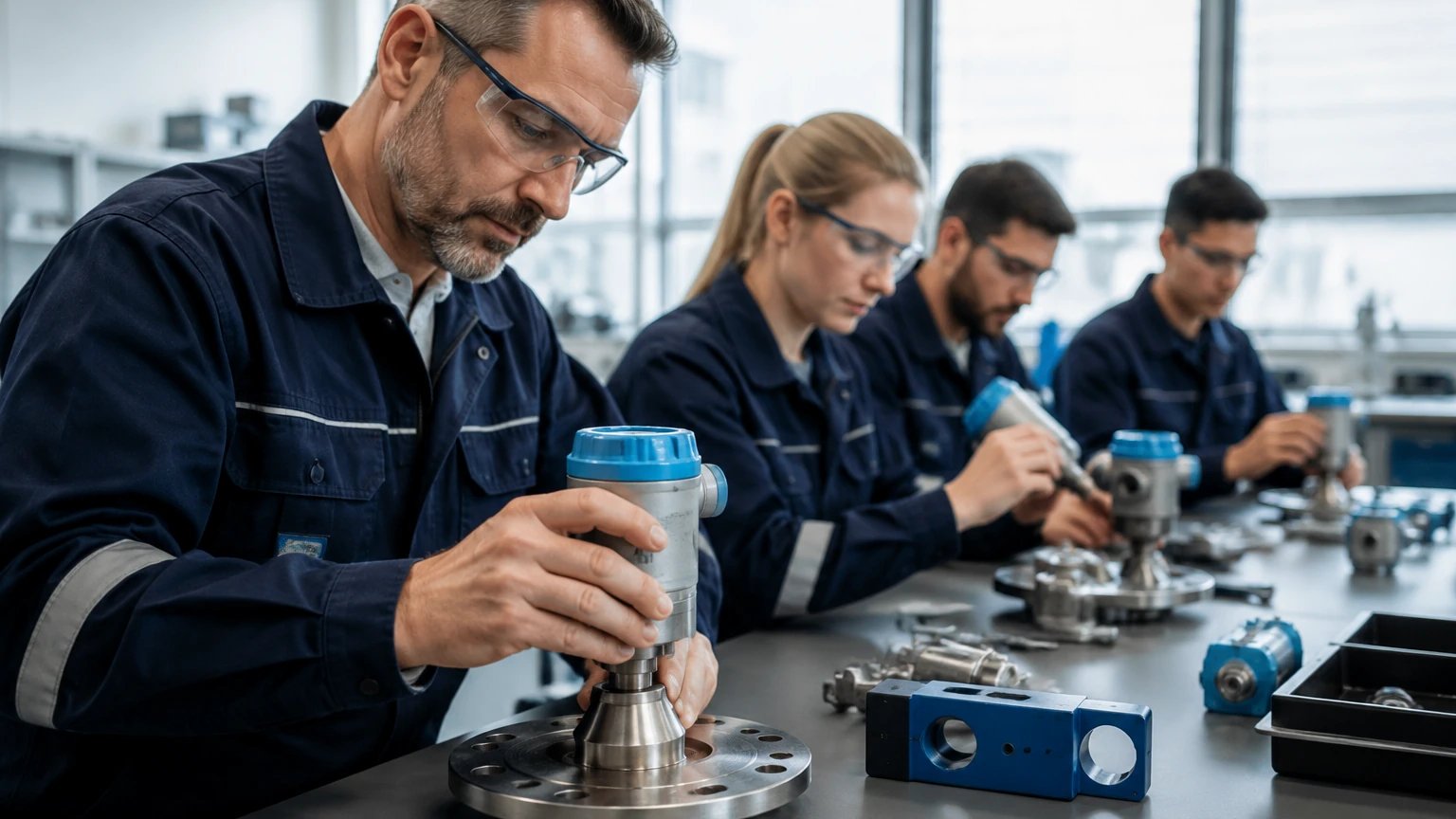
A hands-on instrument & controls course does more than teach theory; it simulates real-world failure modes. In a controlled laboratory environment, students can experience how signal interference, improper grounding, or incorrect mounting affects process data. This practical exposure is vital for minimizing downtime in industrial settings.
Technicians learn to navigate the Main Page of digital configuration tools, mapping 4-20mA signals to specific engineering units and setting up HART (Highway Addressable Remote Transducer) protocols. Understanding how to integrate these instruments into a PLC (Programmable Logic Controller) or DCS (Distributed Control System) is a core competency gained through hands-on practice.
Technical Selection Criteria for Level Instruments
Choosing the right technology is a frequent challenge addressed in any comprehensive hands-on instrument & controls course. The selection depends on the physical properties of the media, vessel geometry, and environmental conditions.
| Technology | Best Suited For | Key Limitations | Typical Accuracy |
| :— | :— | :— | :— |
| Radar (80 GHz) | Small tanks, agitated surfaces, solids | High initial cost | ±1 mm |
| Ultrasonic | Water treatment, open channels | Affected by foam, dust, and vacuum | ±0.25% of range |
| Hydrostatic | Deep wells, vented tanks, constant density | Density changes affect calibration | ±0.1% to ±0.5% |
| Magnetic Gauge | High-pressure boilers, toxic chemicals | Moving parts can wear; requires bypass | ±5 mm |
| Capacitance | Interface measurement, non-conductive liquids | Requires constant dielectric properties | ±0.5% to ±1% |
Installation and Configuration Best Practices
Even the most advanced sensor will fail if installed incorrectly. Professional training emphasizes several critical installation factors:
1. The Blocking Distance (Dead Zone): Every ToF sensor (radar and ultrasonic) has a minimum distance near the face of the sensor where it cannot measure. This must be accounted for when designing tank nozzles.
2. Nozzle Interference: For radar and ultrasonic units, the mounting nozzle should be short and wide enough to prevent the signal from reflecting off the nozzle walls rather than the liquid surface.
3. Beam Angle: Sensors must be mounted away from internal tank obstructions like ladders, agitators, or inflow pipes. A hands-on instrument & controls course teaches students how to use "False Echo Suppression" to digitally mask these static reflections.
4. Hydrostatic Venting: Submersible pressure transducers require a vented cable to compensate for changes in atmospheric pressure. If the vent tube is blocked or kinked, the level reading will drift.
Environmental and Media Limitations
Understanding the boundaries of each technology is essential for process safety.
* Foam: Heavy, dense foam can absorb ultrasonic and radar signals, leading to a "loss of echo." In these cases, Guided Wave Radar or Hydrostatic sensors are preferred.
* Vapor and Pressure: High-pressure steam can change the speed of sound, making ultrasonic sensors inaccurate. Radar is generally unaffected by vapor because microwaves do not require a medium for travel.
* Temperature Extremes: While magnetic level gauges can handle very high temperatures (up to 450°C), electronic sensors like ultrasonic transducers are typically limited to below 80°C to protect the sensitive piezo-elements.
Maintenance and Troubleshooting Procedures
In a hands-on instrument & controls course, troubleshooting is often the most valued module. Technicians are taught to follow a systematic approach:
* Loop Check: Verify that the 4-20mA loop has sufficient voltage (typically 24V DC) and that the resistance is within the allowable range for the controller.
* Signal Validation: Using a communicator to check the "echo curve" or "envelope curve" on a radar meter. A healthy curve shows a distinct peak at the product surface with minimal noise.
* Cleaning Cycles: In applications involving wastewater or crystallization, sensors may require periodic cleaning. Training covers the use of automatic spray systems or protective coatings to reduce maintenance frequency.
Evaluating a Hands-on Instrument & Controls Course
When selecting a training program for staff or personal development, ensure the curriculum covers the following practical aspects:
* Multi-Vendor Equipment: Exposure to various brands, such as Welk or other industry leaders, helps technicians adapt to different interfaces.
* Real Process Loops: The course should feature actual pumping stations or pressurized vessels, not just bench-top simulators.
* Digital Integration: Training must include modern communication protocols like Modbus, Profibus, and Foundation Fieldbus, in addition to standard analog signals.
* Safety Standards: Instruction on SIL (Safety Integrity Level) ratings and hazardous area classifications (ATEX/IECEx) is mandatory for industrial environments.
Frequently Asked Questions (FAQ)
Q: Can I use one sensor for all types of liquids?
No. For example, an ultrasonic sensor may work perfectly for water but fail in a tank of sulfuric acid that produces heavy fumes. Selection must always be based on the specific chemical and physical properties of the media.
Q: What is the difference between 26 GHz and 80 GHz radar?
80 GHz radar has a much narrower beam angle, which allows it to avoid internal obstructions and measure more accurately in small or complex vessels compared to 26 GHz models.
Q: Why is my hydrostatic level transmitter showing a negative value?
This usually occurs if the atmospheric pressure compensation (the vent tube) is compromised or if the sensor was zero-calibrated incorrectly while submerged.
Q: Does foam always stop a radar meter from working?
Not necessarily. While light foam might be transparent to radar, thick, dielectric foam can reflect or attenuate the signal. Guided Wave Radar is often the best solution for foamy applications as the probe concentrates the energy.
By completing a hands-on instrument & controls course, professionals gain the confidence to select the right tool for the job and the skills to keep industrial processes running smoothly. For those looking to explore specific hardware options and technical specifications, visiting a dedicated Main Page for level measurement technology is the best next step in the procurement and engineering process.