Hauser Automation
Hauser Automation
In the landscape of modern industrial processing, the integration of precise field instrumentation into centralized control systems is the cornerstone of operational efficiency. Often discussed within the context of Hauser automation and similar high-level process control frameworks, the ability to accurately monitor material levels—whether liquid, solid, or slurry—is critical for safety, inventory management, and process optimization.
For engineers and plant managers, understanding how level measurement technologies interface with automated environments is essential. This guide explores the fundamental principles of level sensing, the criteria for selecting instruments within an automation architecture, and the practical considerations for ensuring long-term reliability.
The Role of Level Measurement in Industrial Automation
Industrial automation relies on a continuous loop of data: sensing, processing, and acting. Level meters serve as the primary "senses" of this loop. In an automated facility, a level sensor does more than provide a local reading; it transmits real-time data to a Programmable Logic Controller (PLC) or Distributed Control System (DCS).
When implementing Hauser automation strategies, the focus is on reducing human intervention and minimizing error. High-quality level transmitters allow for automated pump control, overfill prevention, and precise batching. By selecting the correct measurement technology, facilities can achieve higher throughput and maintain stricter compliance with environmental and safety regulations.
Core Measurement Principles for Automated Systems
Before selecting hardware for an automated process, it is vital to understand the physics behind the measurement. Different media and environmental conditions require specific sensing methods.
Radar Level Measurement (Time of Flight)
Radar level meters operate on the Time of Flight (ToF) principle. The instrument emits a high-frequency electromagnetic wave (typically in the 26 GHz or 80 GHz range) toward the product surface. The wave reflects off the surface and returns to the sensor.
* The Formula: Distance = (Speed of Light × Time) / 2.
* Advantages: Since radar waves do not require a medium for travel, they are unaffected by vacuum, pressure, or temperature fluctuations. They are ideal for non-contact measurement in volatile or corrosive environments.
Ultrasonic Level Measurement
Similar to radar, ultrasonic sensors use the ToF principle but utilize sound waves instead of electromagnetic waves. The sensor pulse travels at the speed of sound (approximately 340 m/s in air at 20°C).
* Considerations: The speed of sound is affected by air temperature, requiring integrated temperature compensation. Ultrasonic sensors are highly cost-effective for water treatment and open-channel flow but may struggle in heavy dust or foam conditions.
Hydrostatic Level Measurement
This principle relies on the relationship between liquid height and the pressure exerted at the base of a vessel.
* The Formula: P = ρgh (Pressure = Density × Gravity × Height).
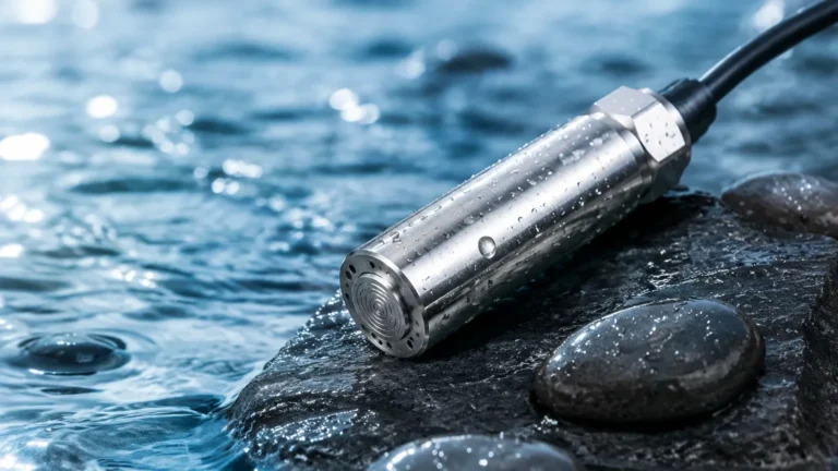
* Application: Hydrostatic transmitters are contact-based and are frequently used in deep wells, tanks, and reservoirs where a constant density is maintained.
Magnetic Level Gauges
Magnetic gauges use a float containing a permanent magnet that moves with the liquid level. This float interacts with an external indicator or a reed-chain transmitter. This provides both a visual reference for operators and a 4-20mA signal for the automation system.
Evaluating Technologies for Hauser Automation Frameworks
When integrating level sensors into a broader Hauser automation environment, the choice of technology is dictated by the physical properties of the material and the vessel geometry.
| Feature | Radar (Non-Contact) | Ultrasonic | Hydrostatic | Magnetic Gauge |
| :— | :— | :— | :— | :— |
| Accuracy | ±1 mm to ±5 mm | ±0.25% of range | ±0.1% to ±0.5% | ±5 mm to ±10 mm |
| Max Range | Up to 120 m | Up to 30 m | Up to 200 m (Cable) | Up to 6 m (Standard) |
| Pressure Limit | High (Up to 160 bar) | Low (Atmospheric) | High (Submersible) | High (Up to 250 bar) |
| Temp. Limit | -40°C to +450°C | -40°C to +80°C | -20°C to +80°C | -196°C to +400°C |
| Media Type | Liquids, Solids, Slurries | Liquids, Some Solids | Liquids only | Clean Liquids |
For a comprehensive look at available instrumentation and technical support, you can Review product options and application support to find the specific model suited for your infrastructure.
Communication Protocols and System Integration
In the context of Hauser automation, the physical measurement is only half of the requirement. The instrument must communicate effectively with the control layer. Modern level meters typically support several standardized protocols:
1. 4-20mA HART: The industry standard. It combines a traditional analog signal with digital information, allowing for remote configuration and diagnostics.
2. Modbus RTU/TCP: Common in water treatment and smaller automation cells due to its simplicity and low cost of implementation.
3. Profibus/PROFINET: Often found in large-scale manufacturing plants requiring high-speed data exchange and complex device profiles.
4. Foundation Fieldbus: Used in the oil and gas sector for its robust diagnostic capabilities and ability to power multiple devices on a single segment.

Installation Guidelines for Automated Level Sensors
Even the most advanced sensor will fail if installed incorrectly. When designing an automated loop, consider the following engineering constraints:
* Blocking Distance (Dead Zone): Every non-contact sensor has a minimum distance near the antenna where measurement is impossible. Ensure the maximum fill level does not enter this zone.
* Nozzle Geometry: For radar and ultrasonic sensors, the nozzle should be short and wide enough to prevent the signal from reflecting off the nozzle walls rather than the product surface.
* Obstructions: Avoid installing sensors directly above agitators, heating coils, or ladders. If obstructions are unavoidable, use instruments with "False Signal Suppression" software to map out static echoes.
* Mounting Angle: Sensors should generally be mounted perpendicular to the liquid surface. For solids, the angle of repose must be considered, often requiring aiming flanges.
Limitations and Risk Mitigation
While automation significantly improves reliability, there are inherent risks that must be managed:
* Signal Loss in Foam: Heavy, dense foam can absorb ultrasonic and radar signals. In such cases, a guided wave radar (GWR) or a hydrostatic transmitter is often a better choice.
* Vapor and Condensation: High humidity can cause condensation on ultrasonic transducers, leading to erratic readings. Radar sensors with PTFE-faced antennas are more resistant to buildup.
* Dielectric Constant (Dk): Radar measurement depends on the Dk value of the medium. Materials with a Dk below 1.4 (like certain liquefied gases) require specialized high-sensitivity radar or GWR.
* Redundancy: In safety-critical applications (e.g., toxic chemical storage), it is best practice to use two different measurement principles (e.g., radar for continuous level and a tuning fork switch for high-level alarm) to prevent common-mode failures.
Frequently Asked Questions (FAQ)
Q: How does Hauser automation handle signal noise in level sensing?
A: Most modern automation-ready level meters include digital filtering algorithms. These allow the user to set damping times, which smooth out fluctuations caused by surface turbulence or agitator blades.
Q: Can I use a single level meter for both control and safety shutdown?
A: While possible, it is not recommended for high-risk environments. Safety standards like SIL (Safety Integrity Level) often require a dedicated, independent sensor for the safety instrumented function (SIF) that is separate from the basic process control system.
Q: What is the maintenance schedule for automated level transmitters?
A: Non-contact sensors like radar require very little maintenance. However, contact-based systems like hydrostatic sensors or magnetic floats should be inspected annually for scaling, corrosion, or mechanical wear.
Q: How do I calibrate a sensor that is already integrated into a PLC?
A: Many instruments allow for "dry calibration" via HART or Modbus, where the zero and span are set based on the vessel dimensions. However, a physical "wet check" (comparing the reading to a manual dip tape) is recommended during commissioning to verify the automation loop's accuracy.
Conclusion
Implementing Hauser automation principles in level measurement requires a balanced approach between selecting the right physical sensing technology and ensuring robust digital integration. By understanding the strengths and limitations of radar, ultrasonic, and hydrostatic principles, engineers can build systems that are not only accurate but also resilient to the challenges of the industrial environment. For further technical specifications and to explore a wide range of industrial level solutions, visit the Main Page of our product catalog.