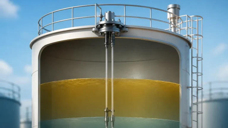
High Pressure Flow Sensor
High Pressure Flow Sensor
In industrial process control, the measurement of fluid movement under extreme force requires specialized instrumentation designed to withstand mechanical stress while maintaining high accuracy. A high pressure flow sensor is a critical component in systems where operating pressures exceed standard commercial limits, often reaching 100 bar (1,450 psi) to 1,000 bar (14,500 psi) or higher. These sensors are foundational in sectors such as oil and gas extraction, chemical synthesis, hydraulic power systems, and high-pressure water treatment.
Selecting the appropriate technology for high-pressure applications involves more than just verifying a pressure rating. It requires an understanding of how fluid density, viscosity, and velocity interact with the sensor’s physical structure under load. This guide examines the primary measurement principles, selection criteria, and installation best practices for high-pressure flow measurement.
Measurement Principles for High-Pressure Environments
Not all flow measurement technologies are suitable for high-pressure environments. The mechanical integrity of the sensor housing and the internal sensing elements must be prioritized to prevent catastrophic failure or leakage. The following principles are most commonly adapted for high-pressure service.
Differential Pressure (DP) Flow Meters
Differential pressure remains one of the most reliable methods for high-pressure applications. This principle relies on Bernoulli’s equation, where a physical constriction (such as an orifice plate, Venturi tube, or flow nozzle) is placed in the flow stream. As the fluid passes through the constriction, its velocity increases and its pressure decreases.
In a high-pressure flow sensor setup using DP, the primary element must be manufactured from thick-walled materials to prevent deformation. The pressure difference is measured by a DP transmitter connected via impulse lines. Because the transmitter itself is often isolated from the main flow by these lines, it is easier to protect the electronics from the extreme conditions of the process pipe.
Coriolis Mass Flow Meters
Coriolis meters are highly valued for their ability to measure mass flow directly, regardless of changes in fluid density or temperature. The principle involves vibrating a tube (or tubes) through which the fluid flows. The mass of the moving fluid causes a slight twisting of the tube due to the Coriolis effect, which is proportional to the mass flow rate.
For high-pressure service, Coriolis sensors utilize heavy-walled measuring tubes. While this increases the durability of the sensor, it also requires more powerful drive coils to maintain the vibration frequency. These sensors are ideal for high-pressure chemical injection or custody transfer of compressed gases.
Vortex Shedding Flow Meters
Vortex meters operate on the Von Kármán effect. A "bluff body" is placed in the flow path, causing vortices to shed alternately on either side. The frequency of these vortices is directly proportional to the fluid velocity. In high-pressure steam or gas applications, vortex sensors are preferred because they have no moving parts that can wear out under high-velocity, high-pressure conditions. The sensor body is typically a solid casting designed to meet high-pressure flange ratings.
Thermal Mass Flow Meters
Thermal mass sensors measure the heat dissipation from a heated element immersed in the flow stream. In high-pressure gas applications, the increased density of the gas improves the heat transfer efficiency, often allowing for very sensitive measurements at the lower end of the flow range. However, the probe must be designed with high-strength seals (such as glass-to-metal seals) to prevent the process gas from entering the electronics housing.
Key Evaluation Criteria for Selection
When specifying a high pressure flow sensor, engineers must evaluate several technical parameters to ensure long-term reliability and safety. Failure to account for these factors can lead to measurement drift or mechanical failure.
| Criterion | Consideration for High Pressure |
| :— | :— |
| Design Pressure vs. Operating Pressure | The sensor must have a design pressure (and burst pressure) significantly higher than the maximum expected operating pressure, typically following a 1.5x or 4x safety factor. |
| Material Compatibility | High pressure can accelerate corrosion and hydrogen embrittlement. Materials like 316L Stainless Steel, Monel, or Hastelloy are often required. |
| Seal Integrity | Traditional O-rings may fail under high pressure. Metal-to-metal seals or specialized high-pressure gaskets (e.g., ring type joints) are preferred. |
| Fluid State | At high pressures, gases may reach a supercritical state where their properties change rapidly. The sensor must be calibrated for these specific conditions. |
| Pressure Drop | Some high-pressure systems have limited pump head. Sensors like orifice plates cause significant pressure loss, whereas Coriolis or Ultrasonic sensors offer a clearer path. |
For a comprehensive look at how these sensors integrate into broader industrial systems, you can Review product options and application support on the Welk Main Page.
Practical Selection Table
The following table provides a comparison of common high-pressure flow measurement technologies based on typical industrial performance limits.
| Technology | Typical Max Pressure | Accuracy (Typical) | Best For | Limitations |
| :— | :— | :— | :— | :— |
| Orifice Plate (DP) | Up to 400 bar+ | ±1.0% to 2.0% | Steam, Clean Liquids | High pressure drop; wear on plate edge. |
| Coriolis | Up to 350 bar | ±0.1% | High-value chemicals, Gases | High initial cost; heavy weight. |
| Vortex | Up to 250 bar | ±0.75% | High-temp steam, Gases | Requires minimum Reynolds number. |
| Turbine | Up to 1000 bar | ±0.25% | Lubricating oils, Water | Moving parts subject to wear. |
| Thermal Mass | Up to 100 bar | ±1.0% | Low-flow gas detection | Sensitive to moisture/droplets. |
Installation Considerations and Safety
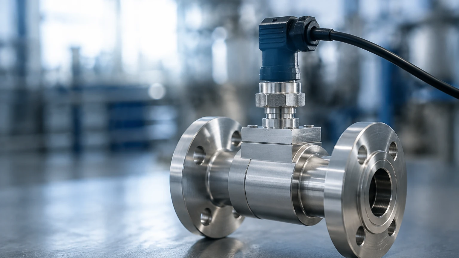
Installing a high pressure flow sensor requires strict adherence to safety protocols. Because the energy stored in a pressurized fluid is significant, any leak or component failure can be hazardous.
1. Mounting and Orientation: Most high-pressure sensors require specific straight-run pipe lengths (typically 10-20 diameters upstream and 5 diameters downstream) to ensure a stable flow profile. For liquid applications, the sensor should be installed in a low point of the piping to ensure it remains full. For gas, it should be at a high point to avoid condensate buildup.
2. Sealing and Connections: Standard NPT threads are often insufficient for pressures above 100 bar in industrial settings. Flanged connections (ANSI/ASME B16.5) or specialized high-pressure fittings (such as Autoclave or HiP fittings) are standard. Ensure all bolts are torqued to the manufacturer's specifications using a calibrated torque wrench.
3. Bypass Loops: In critical processes, installing the flow sensor in a bypass loop with isolation valves allows for maintenance or calibration without shutting down the entire high-pressure line. This is particularly important for sensors with moving parts, like turbine meters.
4. Leak Testing: After installation, the system should undergo a hydrostatic test at 1.5 times the operating pressure. This ensures that all joints, seals, and the sensor body itself are secure before the introduction of hazardous process fluids.
Limitations and Common Risks
While modern engineering has made high-pressure measurement safer, certain inherent limitations remain:
* Signal Noise: High-pressure pumps, especially reciprocating pumps, can create significant pulsations in the flow. This "noise" can interfere with the readings of DP and Vortex sensors. Pulsation dampeners are often required upstream of the sensor.
* Calibration Drift: Under extreme pressure, the physical dimensions of a flow sensor can change slightly (e.g., the expansion of a Coriolis tube). This can lead to a shift in the zero point or the flow factor. Regular field verification or factory recalibration is necessary.
* Cavitation and Flashing: In high-pressure liquid systems, a significant pressure drop across a sensor (like an orifice plate) can cause the liquid to vaporize (flash) or form bubbles (cavitation). This not only destroys measurement accuracy but can also erode the sensor internals rapidly.
Frequently Asked Questions (FAQs)
Q: Can a standard flow sensor be used in a high-pressure line if the flow rate is low?
A: No. The pressure rating of a sensor is independent of the flow rate. A sensor must be rated for the maximum static pressure of the system regardless of how fast the fluid is moving. Using a low-pressure sensor in a high-pressure line can result in the housing bursting.
Q: How does fluid density affect high-pressure gas measurement?
A: At high pressures, gases become much denser. This increases the Reynolds number, which generally helps technologies like Vortex and DP meters. However, it also means the mass flow is much higher for the same volume, which may require a sensor with a wider turndown ratio.
Q: What materials are best for high-pressure hydrogen flow?
A: Hydrogen at high pressure can cause embrittlement in many steels. Specialized stainless steels with high nickel content or specific annealing processes are required to ensure the high pressure flow sensor does not become brittle and crack over time.
Q: Is it better to use a clamp-on ultrasonic meter for high-pressure pipes?
A: Clamp-on meters are attractive because they don't require cutting the pipe. However, high-pressure pipes are often very thick, which can attenuate the ultrasonic signal. Furthermore, the acoustic coupling between the sensor and a thick-walled pipe must be perfect to get an accurate reading.
Conclusion
Selecting a high pressure flow sensor requires a balanced evaluation of mechanical durability, measurement accuracy, and process safety. By understanding the underlying principles—whether it be the mass flow capabilities of a Coriolis meter or the rugged simplicity of a differential pressure system—engineers can implement solutions that withstand the rigors of high-pressure industrial environments. Always consult the manufacturer's pressure-temperature curves to ensure the selected instrument is operating within its safe envelope. For further technical specifications and product comparisons, visit the Main Page to explore professional-grade measurement solutions.