Carbon Capture Equipment
Carbon Capture Equipment
Carbon Capture, Utilization, and Storage (CCUS) has transitioned from a theoretical climate mitigation strategy to a critical industrial requirement. As global regulations tighten, the deployment of carbon capture equipment across power generation, cement manufacturing, and steel production has accelerated. Effective operation of these systems relies heavily on precise process control, where level measurement plays a foundational role in managing chemical solvents, liquefied gases, and phase separation units.
In industrial carbon capture, the primary objective is to isolate carbon dioxide (CO2) from flue gases or process streams. This involves complex chemical and physical interactions that occur within large-scale vessels. Monitoring the levels of fluids within these vessels is not merely a matter of inventory; it is essential for safety, efficiency, and the prevention of equipment damage.
Understanding the Role of Level Measurement in Carbon Capture Equipment
Carbon capture equipment typically utilizes chemical absorption, physical adsorption, or membrane separation. The most common commercial method is amine-based chemical absorption. In this process, flue gas passes through an absorber tower where a solvent (usually an amine solution) reacts with the CO2. The "rich" solvent is then pumped to a stripper (regenerator) where heat is applied to release the CO2, allowing the "lean" solvent to be recycled.
Level measurement is required at several critical points:
1. Absorber Sumps: Ensuring the correct level of solvent to prevent pump cavitation and maintain gas-liquid contact efficiency.
2. Flash Tanks: Managing the separation of CO2 from the solvent as pressure is reduced.
3. Reflux Drums: Monitoring the condensed water and solvent at the top of the stripper.
4. Storage Tanks: Tracking the inventory of captured CO2, often in a liquefied state under high pressure and low temperature.
Measurement Principles for CCUS Environments
Before selecting specific instrumentation, it is vital to understand the physics behind the measurement technologies used in carbon capture equipment. Each principle offers distinct advantages depending on the physical properties of the media, such as dielectric constant, density, and turbulence.
Radar Level Measurement (ToF)
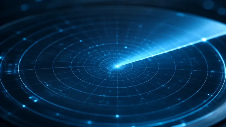
Radar sensors operate on the Time-of-Flight (ToF) principle. They emit high-frequency microwave pulses (typically in the 24 GHz or 80 GHz range) that travel at the speed of light. When these pulses hit the surface of the medium, they are reflected back to the sensor. The distance is calculated based on the time interval between emission and reception.
* Non-contact Radar: Ideal for corrosive amine solutions as the sensor does not touch the medium. 80 GHz technology is preferred for its narrow beam angle, which avoids internal obstructions like agitators or spray headers.
* Guided Wave Radar (GWR): Uses a physical probe to guide the microwave. This is highly effective for low-dielectric media like liquefied CO2, as the probe concentrates the energy, ensuring a stronger return signal even with weak reflections.
Ultrasonic Level Measurement
Ultrasonic sensors emit sound waves that reflect off the liquid surface. The time taken for the echo to return determines the level. While cost-effective, these are generally limited to atmospheric pressure tanks and can be affected by the gas composition above the liquid. In carbon capture, where CO2 concentrations vary, the speed of sound changes, which can lead to measurement errors unless temperature and gas-density compensation are applied.
Hydrostatic Pressure Measurement
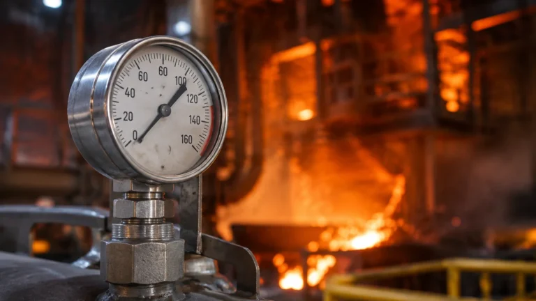
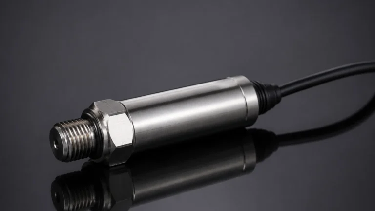
This principle measures the pressure exerted by a liquid column. The level is calculated using the formula: *Level = Pressure / (Density × Gravity)*. In carbon capture equipment, this is often used in pressurized vessels using a differential pressure (DP) setup to compensate for the head pressure of the gas phase.
Magnetic Level Gauges
Operating on the principle of buoyancy and magnetic coupling, a float containing a magnet moves with the liquid level inside a bypass chamber. An external indicator or transmitter tracks the float's position. This provides a robust, visual local indication that is independent of power supply, which is critical for safety-instrumented systems (SIS).
Selecting Level Instrumentation for Specific Capture Processes
Choosing the right instrument requires matching the technology to the specific process conditions of the carbon capture equipment. The following table provides a general selection guide based on common applications.
Selection Matrix for Carbon Capture Applications
| Application | Medium | Typical Conditions | Recommended Technology | Why? |
| :— | :— | :— | :— | :— |
| Absorber Tower Sump | Amine Solvent | 40°C – 60°C, Low Pressure | Non-contact Radar (80 GHz) | Resists corrosion; ignores foam and turbulence. |
| Stripper/Regenerator | Rich Amine | 100°C – 120°C, Moderate Pressure | Guided Wave Radar | Handles steam and high-temperature vapors effectively. |
| CO2 Flash Tank | Liquid/Gas CO2 | Variable Pressure | Differential Pressure or GWR | Reliable in high-pressure phase separation. |
| Liquid CO2 Storage | Liquefied CO2 | -20°C to -50°C, 20+ bar | Magnetic Level Gauge w/ Transmitter | Redundant visual and electronic tracking for safety. |
| Solvent Makeup Tank | Fresh Amine | Ambient | Ultrasonic or Radar | Simple, cost-effective inventory management. |
For engineers looking to integrate these technologies into a broader automation strategy, it is helpful to Review product options and application support on our Main Page to ensure compatibility with specific chemical compositions.
Technical Challenges and Limitations in CO2 Monitoring
While the principles of level measurement are well-established, carbon capture equipment presents unique challenges that can interfere with accuracy.
1. Low Dielectric Constant of CO2
Liquid CO2 has a very low dielectric constant (εr ≈ 1.6). Standard non-contact radar may struggle to receive a strong enough reflection from the surface. In these instances, Guided Wave Radar (GWR) or high-sensitivity 80 GHz radar is necessary to ensure signal integrity.
2. Foam Formation
In amine scrubbers, impurities or high gas velocities can lead to significant foam formation. Ultrasonic sensors will fail in these conditions as the foam absorbs the sound waves. Radar, particularly at lower frequencies or with advanced signal processing, can often "see through" light foam to the true liquid level, though heavy, dense foam may still require GWR.
3. High Pressure and Supercritical States
In the compression stage of carbon capture equipment, CO2 may reach a supercritical state where the boundary between liquid and gas disappears. Level measurement becomes impossible in the traditional sense, and mass flow or density measurement must be used instead. For high-pressure liquid storage, instruments must be rated for PN63, PN100, or higher, with specialized seals to prevent CO2 leakage.
4. Material Compatibility
Amine solutions, particularly when "rich" with CO2, can be corrosive to certain metals and elastomers. Stainless steel (316L) is typically the minimum requirement for wetted parts, while PTFE or PFA coatings are often used for radar antennas to prevent chemical attack.
Installation and Maintenance Best Practices
Proper installation is as critical as technology selection for the longevity of carbon capture equipment instrumentation.
* Nozzle Geometry: For radar installations, ensure the nozzle height does not exceed the manufacturer’s recommendations to prevent "ringing" or internal reflections that create false echoes near the top of the tank.
* Stilling Wells: In vessels with high turbulence or internal structures, installing GWR or non-contact radar inside a stilling well (a vertical pipe) can provide a calm surface for measurement and shield the signal from interference.
* Bypass Chambers: For magnetic level gauges, the bypass chamber should be thermally insulated if the process involves cryogenic liquid CO2 to prevent boiling within the chamber, which would cause inaccurate float positioning.
* Calibration: While radar and ultrasonic sensors are generally "calibration-free" regarding drift, hydrostatic systems require periodic zero-point checks, especially if the density of the solvent changes over time due to degradation or concentration shifts.
Frequently Asked Questions (FAQs)
Q: Can I use a standard ultrasonic sensor for liquid CO2 storage?
A: Generally, no. Liquid CO2 is stored under high pressure, and the gas space above the liquid is pure CO2. The speed of sound in CO2 is significantly different from air, and pressure changes will further alter the sound velocity, leading to massive errors. Radar or magnetic gauges are much more reliable.
Q: How does foam in the absorber affect radar measurement?
A: 80 GHz radar is highly effective at penetrating light foam. However, if the foam is extremely thick and dielectric-rich, it may reflect the signal itself. In such cases, using a Guided Wave Radar with a coaxial probe is the best solution, as it ignores the foam and measures the liquid surface inside the probe.
Q: What is the maintenance cycle for level sensors in amine service?
A: Non-contact sensors like radar require very little maintenance. However, we recommend a visual inspection of the antenna every 12-24 months to check for chemical buildup or scaling, which can occur if the amine solution is not properly filtered.
Q: Is it necessary to use explosion-proof sensors for carbon capture?
A: While CO2 itself is not flammable, the environment (such as a refinery or gas plant) where the carbon capture equipment is located is often classified as a hazardous area (ATEX/IECEx). Therefore, sensors usually need to be intrinsically safe or explosion-proof to comply with site safety standards.
By understanding these measurement principles and the specific demands of the CCUS process, engineers can ensure that their carbon capture equipment operates at peak efficiency, contributing to both environmental goals and operational profitability.