High Temperature Pressure Sensor
High Temperature Pressure Sensor
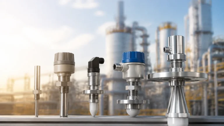
In industrial process control, pressure measurement is a fundamental requirement for safety, efficiency, and quality management. However, when process temperatures exceed the standard operating range of conventional electronics—typically above 85°C to 100°C—standard sensors often fail or provide inaccurate data. A specialized high temperature pressure sensor is engineered to withstand these thermal extremes while maintaining signal integrity. These instruments are critical in applications ranging from steam boiler monitoring and chemical synthesis to oil refining and plastic extrusion.
Selecting the right high-temperature solution requires an understanding of how heat affects sensor materials and electrical components. This guide examines the measurement principles, design architectures, and installation strategies necessary for reliable pressure monitoring in high-heat environments.
Principles of High-Temperature Pressure Measurement
Pressure sensors convert mechanical force into an electrical signal. In high-temperature environments, the primary challenge is preventing the heat from degrading the sensing element or the internal electronics. Several technologies are utilized to achieve this balance.
Piezoresistive Sensors (Silicon-on-Insulator)
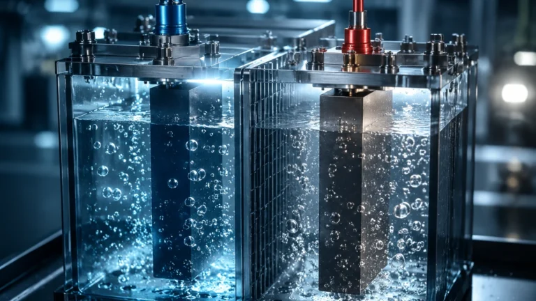
Standard piezoresistive sensors use silicon strain gauges diffused into a silicon diaphragm. At high temperatures, the P-N junctions in standard silicon leak current, leading to signal failure. High-temperature variants often utilize Silicon-on-Insulator (SOI) technology. By adding an insulating layer of silicon dioxide between the sensing elements and the substrate, the sensor can operate at significantly higher temperatures—often up to 200°C or higher—without electrical leakage.
Thin-Film Strain Gauges
Thin-film sensors are manufactured by depositing a layer of resistive material onto a stainless steel or ceramic diaphragm using sputtering techniques. Because the materials used (such as nickel-chromium alloys) have high melting points and stable thermal coefficients, thin-film sensors are exceptionally robust. They are frequently used in applications reaching 150°C to 250°C. Their long-term stability and resistance to vibration make them a preferred choice for heavy industrial machinery.
Capacitive Pressure Sensing
Capacitive sensors measure the change in electrical capacitance between a flexible diaphragm and a fixed electrode. Since this method does not rely on bonded strain gauges, it is less susceptible to the thermal expansion mismatches that can plague other designs. Ceramic capacitive sensors are particularly effective in high-temperature and corrosive environments because the ceramic material itself is both chemically inert and thermally stable.
Key Design Features for Thermal Resistance
To manage extreme heat, a high temperature pressure sensor often incorporates physical design modifications that isolate the sensitive electronics from the process media.
Integrated Cooling Fins
Cooling fins (or heat sinks) are machined into the sensor body between the process connection and the electronics housing. These fins increase the surface area of the sensor, allowing ambient air to dissipate heat before it reaches the internal circuitry. This passive cooling method can reduce the temperature at the sensor head by dozens of degrees Celsius.
Diaphragm Seals and Capillaries
In cases where the process temperature exceeds 300°C or 400°C, a remote diaphragm seal is often employed. The pressure is transmitted from a metal diaphragm at the process point through a liquid-filled capillary tube to a pressure transmitter located in a cooler environment. The choice of fill fluid is critical; specialized silicone oils or synthetic liquids with high boiling points and low thermal expansion coefficients are used to ensure that the pressure transfer remains accurate despite the heat.
Material Selection
The wetted parts of the sensor must resist both the pressure and the potential for thermal oxidation or corrosion. Common materials include:
- 316L Stainless Steel: Standard for moderate temperatures and non-corrosive media.
- Hastelloy C-276: Used for high-temperature applications involving aggressive chemicals.
- Inconel: Ideal for extreme heat environments where high strength and oxidation resistance are required.
Selection Criteria and Technical Specifications
When evaluating a high temperature pressure sensor for a specific application, engineers must consider several technical parameters beyond the basic pressure range. For a broader overview of industrial instrumentation and to explore specific product models, engineers can refer to the Main Page of professional equipment manufacturers.
Operating vs. Compensated Temperature Range
It is vital to distinguish between the operating temperature (the range where the sensor will not be damaged) and the compensated temperature (the range where the sensor meets its accuracy specifications). High-quality sensors include internal temperature compensation circuits that correct for thermal zero shift and sensitivity shift.
Accuracy and Thermal Drift
All sensors experience some degree of "drift" as temperature changes. This is usually expressed as a percentage of the Full Scale (FS) per degree Celsius. For example, a sensor might have a thermal zero shift of <±0.02% FS/°C. In high-precision B2B applications, minimizing this drift is essential for process consistency.
Output Signals
Standard industrial outputs include 4-20 mA current loops, 0-10 VDC, or digital protocols like HART, Modbus, or Profibus. In high-temperature environments, 4-20 mA is often preferred due to its high immunity to electrical noise and its ability to transmit signals over long distances without degradation.
Installation Best Practices for High-Heat Environments
Proper installation is as important as sensor selection. Even the best high temperature pressure sensor can fail prematurely if installed incorrectly.
1. Use of Siphons: For steam applications, a pigtail or U-type siphon should always be used. The siphon traps condensed liquid, which acts as a thermal barrier between the live steam and the sensor element.
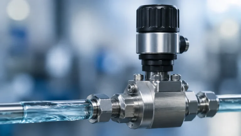
2. Impulse Piping: Increasing the length of the impulse line between the process pipe and the sensor allows for natural convection cooling. A few meters of uninsulated tubing can significantly drop the temperature of the media reaching the sensor.
3. Orientation: Mounting the sensor vertically with the electronics pointing upwards can sometimes lead to heat rising into the housing. In very hot applications, mounting the sensor horizontally or using a 90-degree elbow can help divert rising heat away from the transmitter head.
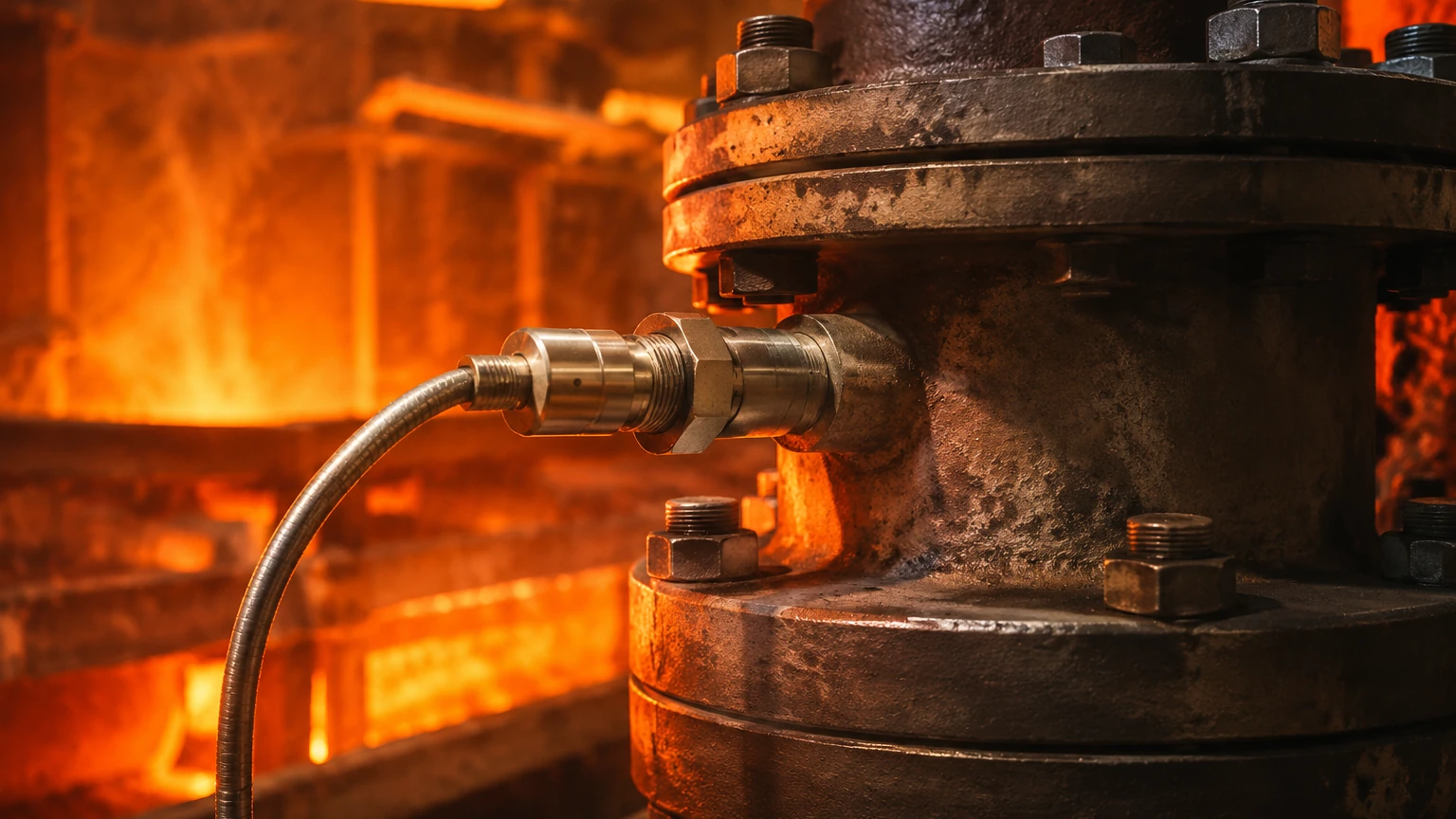
4. Environmental Shielding: If the sensor is located near a radiant heat source (like a furnace wall), heat shields should be installed to protect the electronics housing from infrared radiation.
Limitations and Maintenance Considerations
While high-temperature sensors are robust, they are not indestructible. Users should be aware of the following limitations:
- Thermal Fatigue: Frequent and rapid temperature cycling can cause mechanical stress on the diaphragm and internal bonds, eventually leading to fatigue failure.
- Fill Fluid Degradation: In capillary-based systems, if the temperature exceeds the rating of the fill fluid, the fluid may polymerize or outgas, resulting in a "spongy" response or total loss of signal.
- Calibration Requirements: High-temperature sensors often require more frequent calibration checks than their room-temperature counterparts. Thermal aging can cause subtle shifts in the sensor's output over time.
Comparison Table of Sensor Technologies
| Technology | Typical Max Temp (Direct) | Pros | Cons |
| :— | :— | :— | :— |
| Piezoresistive (SOI) | 200°C – 250°C | High sensitivity, compact | Sensitive to electromagnetic interference |
| Thin-Film | 250°C – 300°C | Excellent long-term stability | Lower output signal level |
| Ceramic Capacitive | 150°C – 200°C | High corrosion resistance | Brittle; sensitive to shock |
| Diaphragm Seal | 400°C+ | Isolates electronics entirely | Slower response time; higher cost |
Frequently Asked Questions (FAQ)
Q: Can I use a standard pressure sensor with a long impulse line instead of buying a high-temperature model?
A: Yes, in many cases, a standard sensor can be used if the impulse line is long enough to cool the media to within the sensor's operating range. However, this may introduce lag in the pressure reading and increases the risk of the line clogging if the media solidifies when cooled.
Q: What is the difference between a pressure sensor and a hydrostatic level transmitter in high-heat applications?
A: A hydrostatic level transmitter is a type of pressure sensor calibrated to measure the height of a liquid column. In high-temperature tanks (like pressurized boilers), the transmitter must account for changes in liquid density caused by heat to maintain level accuracy.
Q: How do I protect the electronics from ambient heat?
A: If the ambient air around the sensor is also hot, cooling the process media alone is insufficient. In these cases, look for sensors with remote-mounted electronics or use cooled enclosures (vortex coolers or water-jacketed housings).
Q: Why is my sensor reading drifting even though it is rated for high temperatures?
A: This is likely due to thermal zero shift. While the sensor is rated for the temperature, the heat still causes slight expansions in the materials. Ensure the sensor is properly compensated and that the temperature has stabilized before taking critical measurements.
For technical assistance in selecting the appropriate measurement technology for your specific industrial environment, reviewing the available configurations on the Main Page can provide necessary insights into modern sensor capabilities and integration options.