How to Calibrate a Pressure Transducer
How to Calibrate a Pressure Transducer
In industrial automation and process control, the accuracy of level and pressure measurement is fundamental to operational safety and efficiency. Pressure transducers, which convert physical force into an electrical signal, are the workhorses of these systems. However, like all precision instruments, they are subject to drift over time due to environmental factors, mechanical wear, or electronic aging. Understanding how to calibrate a pressure transducer is a critical skill for maintenance engineers and technicians to ensure that process variables remain within specified tolerances.
Calibration is the process of comparing the output of a measurement device against a known reference standard. For a pressure transducer, this typically involves applying a series of known pressures and verifying that the electrical output (usually 4-20mA or 0-10V) corresponds accurately to those values. This guide provides a comprehensive overview of the principles, procedures, and best practices for calibrating these essential instruments.
Measurement Principles of Pressure Transducers
Before diving into the calibration procedure, it is essential to understand how these devices function. Pressure transducers generally utilize a sensing element that deforms under pressure. This deformation is then converted into an electrical signal through various technologies:
1. Piezoresistive Sensors: These utilize strain gauges bonded to a diaphragm. As pressure is applied, the diaphragm flexes, changing the resistance of the gauges. This change is measured via a Wheatstone bridge circuit.
2. Capacitive Sensors: These measure the change in electrical capacitance between a flexible diaphragm and a fixed metal plate. As the diaphragm moves, the distance—and thus the capacitance—changes.
3. Hydrostatic Level Measurement: In many industrial applications, pressure transducers are used to measure liquid level. This is based on the principle that the pressure at the bottom of a tank is proportional to the height of the liquid column above it, defined by the formula $P = \rho \cdot g \cdot h$ (where $P$ is pressure, $\rho$ is fluid density, $g$ is gravity, and $h$ is the height of the liquid).
Because the transducer relies on these physical and electrical relationships, any shift in the mechanical properties of the diaphragm or the stability of the internal electronics will necessitate recalibration.
Essential Equipment for Calibration
To perform a professional calibration, you will need the following equipment:
* Pressure Source: A hand pump, nitrogen cylinder with a regulator, or a deadweight tester capable of generating the required range.
* Reference Standard: A high-precision digital pressure gauge or calibrator with an accuracy at least four times better than the device under test (DUT).
* Power Supply: Typically a 24V DC source for loop-powered transducers.
* Signal Measurement: A digital multimeter (DMM) capable of measuring mA or Volts with high precision.
* HART Communicator (Optional): Required if the transducer is a "smart" device using the HART protocol for digital adjustments.
Step-by-Step: How to Calibrate a Pressure Transducer
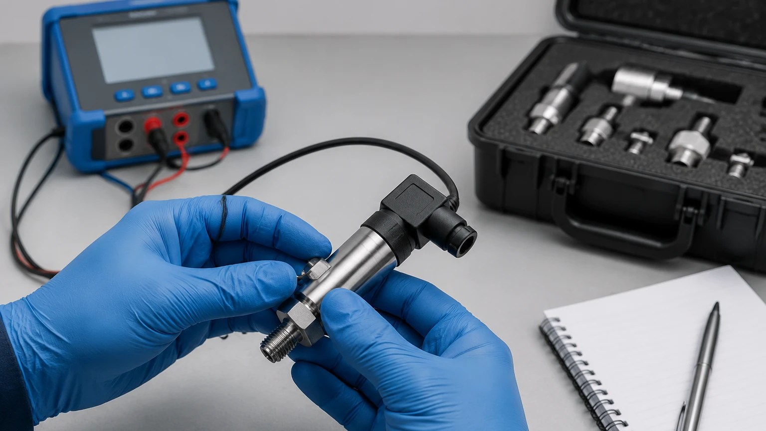
The most common method for industrial calibration is the five-point check. This involves testing the device at 0%, 25%, 50%, 75%, and 100% of its full-scale range, both in increasing and decreasing directions to check for hysteresis.
1. Preparation and Safety
Ensure the transducer is isolated from the process. Bleed off any residual pressure and disconnect the wiring if performing a bench calibration. If calibrating in the field, ensure the control system is placed in manual mode to prevent accidental process upsets.
2. Zero Adjustment
With the transducer open to the atmosphere (zero gauge pressure), check the output signal. For a 4-20mA sensor, the output should be exactly 4.000 mA. If the reading is off, use the "Zero" adjustment screw or the HART communicator to bring the signal to 4.000 mA.
3. Span Adjustment
Apply the maximum rated pressure for the transducer's calibrated range using your pressure source. For example, if the transducer is rated for 0-10 bar (0-145 PSI), apply exactly 10 bar as measured by your reference standard. The output should be 20.000 mA. Use the "Span" adjustment to correct any deviation.
4. Linearity Check (The Five-Point Test)
Once the Zero and Span are set, perform the full check:
* 0%: 4.00mA
* 25%: 8.00mA
* 50%: 12.00mA
* 75%: 16.00mA
* 100%: 20.00mA
Record the actual readings at each point. If the errors at the mid-points are outside the manufacturer's specified accuracy (e.g., ±0.5% FS), the device may have linearity issues that require factory service or replacement.
5. Documenting Results
Calibration is not complete without a certificate. Record the "As-Found" (before adjustment) and "As-Left" (after adjustment) data, the serial numbers of the test equipment used, and the date of calibration.
Selection Criteria for Level and Pressure Instruments
Choosing the right technology is as important as maintaining it. Depending on the media and environment, a standard pressure transducer might not always be the best fit. For more complex applications, engineers often look to the Main Page of specialized manufacturers like Welk to compare different measurement technologies.
| Technology | Best For | Advantages | Limitations |
| :— | :— | :— | :— |
| Hydrostatic Transducer | Vented tanks, water treatment | Low cost, simple installation | Sensitive to density changes |
| Radar Level Meter | Corrosive chemicals, high temp | Non-contact, extremely accurate | Higher initial investment |
| Ultrasonic Sensor | Open channels, liquids | Non-contact, easy to setup | Affected by foam and vapor |
| Magnetic Level Gauge | High-pressure boilers | Highly visible, no power needed | Mechanical moving parts |
Installation Considerations
How a pressure transducer is installed significantly impacts its calibration stability:
* Mounting Position: Some sensitive transducers exhibit a "position effect" where the weight of the internal oil fill or the diaphragm itself shifts the zero point if the device is tilted. Always calibrate the device in the orientation it will be installed.
* Temperature Effects: Extreme ambient temperatures can cause thermal expansion in the sensor. While many Welk instruments include internal temperature compensation, it is best to install transducers away from direct heat sources.
* Impulse Lines: In gas or steam applications, ensure impulse lines are sloped correctly to prevent condensate buildup, which creates a false pressure head and ruins calibration accuracy.
Limitations and Common Risks
While learning how to calibrate a pressure transducer is straightforward, there are risks involved:
* Overpressure: Applying pressure beyond the sensor's proof pressure can permanently deform the diaphragm, leading to non-linear errors that cannot be calibrated out.
* Media Compatibility: Ensure the calibration fluid (e.g., oil or water) is compatible with the transducer's wetted parts and the eventual process media. For oxygen service, transducers must be calibrated using oil-free methods.
* Electronic Drift: In high-EMI (electromagnetic interference) environments, signal noise can be mistaken for calibration drift. Use shielded cables and ensure proper grounding.
Frequently Asked Questions (FAQ)
Q: How often should I calibrate my pressure transducer?
A: Most industrial standards recommend an annual calibration. However, if the process is critical or the environment is harsh (high vibration/temperature), semi-annual or quarterly checks may be necessary.
Q: Can I calibrate a transducer without a pressure source?
A: No. While you can perform a "loop check" to verify the electronics are transmitting the signal correctly, a true calibration requires a physical pressure reference to verify the sensor's mechanical-to-electrical conversion.
Q: What is the difference between a sensor, a transducer, and a transmitter?
A: A sensor is the raw element; a transducer converts that sense into a basic electrical signal (like millivolts); a transmitter amplifies and conditions that signal into a standard industrial format like 4-20mA.
Q: How do I handle density changes in hydrostatic level measurement?
A: Since hydrostatic pressure depends on density, if your fluid density changes (e.g., due to temperature), your level reading will be inaccurate. In these cases, you must either use a compensated system or switch to a technology like radar that is independent of density.
Conclusion
Accurate pressure measurement is the foundation of process safety. By following a rigorous calibration schedule and understanding the underlying physics of your instrumentation, you can prevent costly downtime and ensure product quality. Whether you are using hydrostatic transmitters for water tanks or sophisticated radar systems for chemical processing, proper maintenance is non-negotiable. For those looking to upgrade their current systems or seeking technical specifications for new installations, visiting the Main Page of an established manufacturer like Welk provides access to a wide range of reliable, cost-effective industrial level measurement solutions.