Hydrogen Compressors
Hydrogen Compressors
In the rapidly evolving landscape of the global energy transition, hydrogen compressors serve as the critical link between production, storage, and end-use. Whether hydrogen is generated via electrolysis or steam methane reforming, it must be compressed to high densities for efficient transport and storage. For process engineers and facility managers, understanding the mechanics of hydrogen compression—and the sophisticated instrumentation required to monitor these systems—is essential for ensuring operational safety and efficiency.
Hydrogen is the lightest and smallest molecule in the universe, presenting unique challenges for mechanical compression. It has a low volumetric energy density, meaning large volumes must be compressed to high pressures (often exceeding 700 bar or 10,150 psi) to be commercially viable. This article explores the various types of hydrogen compressors, the engineering principles behind their operation, and the critical role of level measurement in their auxiliary systems.
Core Technologies in Hydrogen Compression
Hydrogen compressors are generally categorized by their mechanical operation. The choice of technology depends on the required flow rate, discharge pressure, and gas purity standards.
Reciprocating Piston Compressors
Reciprocating compressors use a crankshaft-driven piston to compress gas within a cylinder. These are the most common choice for high-pressure hydrogen applications. They can be lubricated or non-lubricated. In hydrogen service, non-lubricated (oil-free) designs are often preferred to prevent contamination of the hydrogen gas, which is vital for fuel cell applications. These units are capable of reaching pressures up to 500 bar (7,250 psi) in multi-stage configurations.
Diaphragm Compressors
A diaphragm compressor is a variant of the reciprocating design where a flexible metal diaphragm separates the hydrogen gas from the hydraulic oil and piston. This ensures zero leakage and zero contamination, making it the "gold standard" for high-purity hydrogen used in refueling stations. These systems often operate at pressures between 350 bar (5,075 psi) and 1,000 bar (14,500 psi). Monitoring the hydraulic oil level and the integrity of the diaphragm is a critical maintenance requirement.
Centrifugal Compressors
Centrifugal compressors use high-speed impellers to add kinetic energy to the gas, which is then converted into pressure. While highly efficient for high-volume flow, hydrogen’s low molecular weight makes it difficult to compress centrifugally. These units require extremely high tip speeds and multiple stages to achieve significant pressure ratios, making them more common in large-scale industrial pipeline transport rather than localized storage.
Ionic Liquid Compressors
An emerging technology, ionic liquid compressors replace the solid piston with a near-incompressible ionic liquid. This reduces the number of moving parts, improves heat dissipation, and eliminates the need for traditional seals. These systems are highly efficient and are increasingly being considered for hydrogen refueling infrastructure.
Measurement Principles in Compressor Auxiliary Systems
While the compressor itself is the heart of the operation, it cannot function without auxiliary systems for lubrication, cooling, and moisture separation. Precise level measurement in these systems is vital for preventing equipment failure. Before selecting a sensor, it is important to understand the underlying measurement principles.
Radar Level Measurement (ToF)
Radar level meters operate on the Time-of-Flight (ToF) principle. A sensor emits a high-frequency electromagnetic wave (typically 80GHz in modern units) that reflects off the surface of the liquid and returns to the receiver. The distance is calculated based on the time taken for the signal to travel.
In hydrogen compressor systems, radar is frequently used in oil-gas separators and condensate tanks. Because it is non-contact, it is unaffected by the high-pressure hydrogen atmosphere, provided the housing is rated for the environment. High-frequency radar is particularly effective at penetrating foam or vapor layers that may form in oil separators.
Hydrostatic Level Measurement
Hydrostatic transmitters measure the pressure exerted by a liquid column at the bottom of a tank. The level is calculated using the formula $L = P / (\rho \cdot g)$, where $P$ is pressure, $\rho$ is the density of the fluid, and $g$ is gravity. In pressurized hydrogen systems, a differential pressure (DP) transmitter is required to compensate for the high overhead gas pressure. This method is robust but requires accurate knowledge of the fluid's density, which can change with temperature.
Magnetic Level Gauges
Magnetic level gauges utilize a float containing a permanent magnet that moves with the liquid level inside a bypass chamber. Outside the chamber, a series of magnetic flags or a transmitter tracks the float's position. This provides a clear visual indication without requiring power, which is a significant safety benefit in hazardous hydrogen zones. For automated control, these can be equipped with reed switches or magnetostrictive transmitters.
The Role of Level Measurement in Compressor Operations
In a hydrogen compression circuit, level measurement is not merely a monitoring task; it is a safety-critical function. There are three primary areas where level instrumentation is indispensable:
1. Lube Oil Management: In reciprocating compressors, the crankcase oil level must be maintained to ensure mechanical longevity. Low levels lead to friction and overheating, while high levels can cause oil carryover into the gas stream.
2. Condensate Separation: As hydrogen is compressed and cooled between stages, moisture or heavy hydrocarbons may drop out of the gas. These liquids collect in separators. If the liquid level rises too high, it can be carried into the next compression stage, potentially causing catastrophic "liquid slugging" which can destroy pistons and valves.
3. Coolant Systems: High-pressure compression generates significant heat. Closed-loop cooling systems require constant level monitoring to ensure that the heat exchangers remain submerged and functional.
For engineers designing these complex systems, sourcing reliable instrumentation from a specialized manufacturer like Welk on their Main Page ensures that every auxiliary tank is monitored with precision.
Selection Table: Level Technologies for Hydrogen Systems
Choosing the right instrument depends on the specific fluid and the process conditions. The following table provides a general guide for selection.
| Technology | Typical Application | Advantages | Limitations |
| :— | :— | :— | :— |
| 80GHz Radar | Oil-Gas Separators | Non-contact, high accuracy, ignores vapor | Expensive; requires top-mounting space |
| Guided Wave Radar | Condensate Tanks | Works well in narrow tanks, high pressure | Contact-based; probe can be affected by buildup |
| Magnetic Gauge | External Storage Tanks | Visual verification, no power needed | Mechanical parts can wear; limited to specific gravities |
| Ultrasonic | Water/Coolant Tanks | Cost-effective, easy to install | Not suitable for high pressure or hydrogen atmospheres |
| Level Switch | High/Low Alarm | Redundant safety, simple integration | Point level only; no continuous data |
| Hydrostatic (DP) | Large Buffer Tanks | Proven technology, handles high pressure | Requires two process connections; density dependent |
Engineering Considerations: Pressure and Material Safety
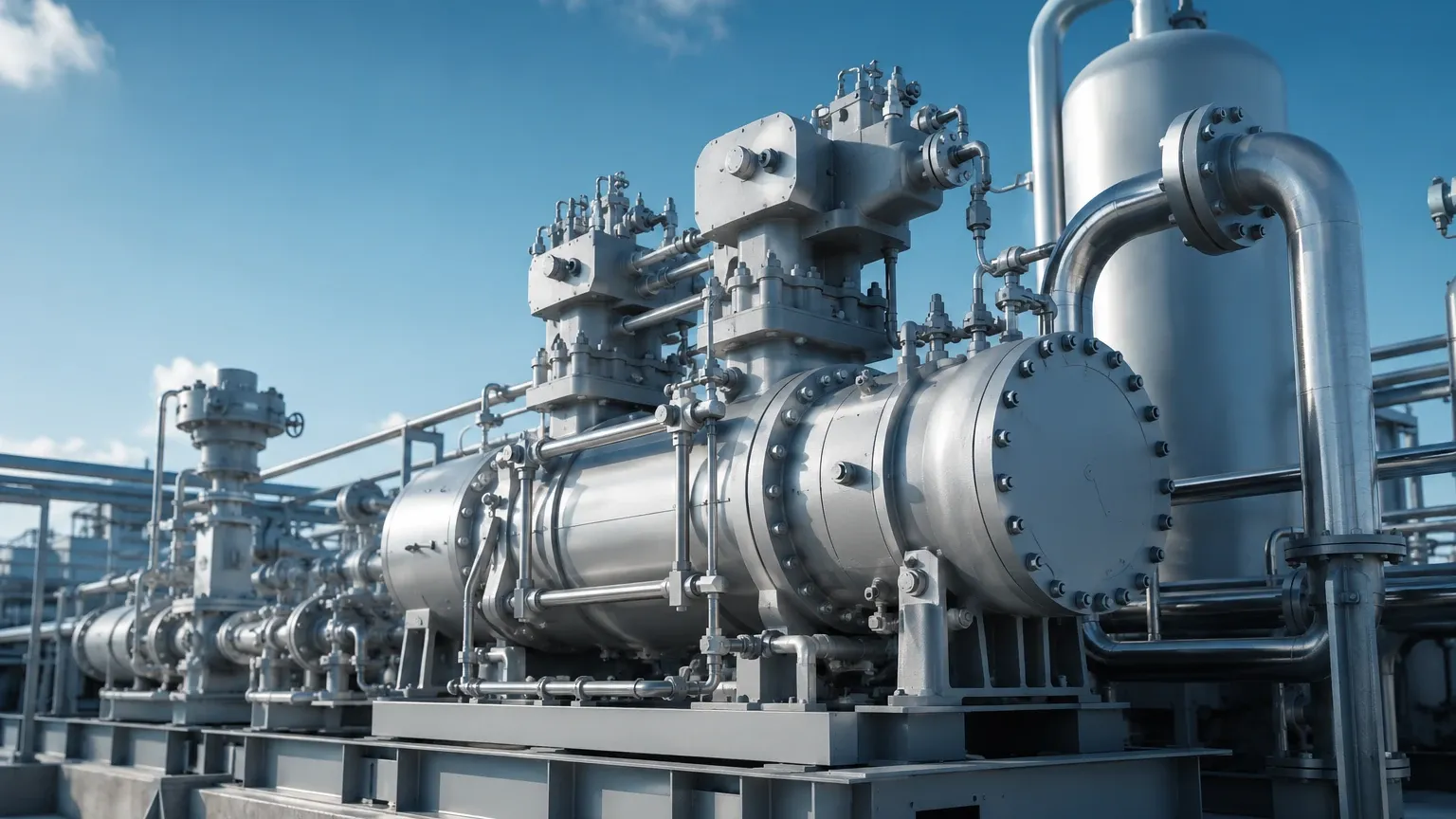
Hydrogen compressors operate under extreme conditions that demand specific material and safety considerations.
Hydrogen Embrittlement
Hydrogen atoms are small enough to diffuse into the crystalline lattice of metals. This can lead to hydrogen embrittlement, where ductile metals become brittle and crack under stress. For any level instrument in contact with hydrogen—such as the probes of guided wave radars or the chambers of magnetic gauges—materials like 316L stainless steel or Hastelloy C276 are required. Standard carbon steels are generally avoided for high-pressure hydrogen service.
Explosion-Proof Requirements
Hydrogen has a very wide flammability range (4% to 75% in air) and a very low ignition energy. Consequently, all electrical instrumentation used near hydrogen compressors must be certified to ATEX, IECEx, or Class/Division standards for Zone 0 or Zone 1 environments (Group IIC). This includes the use of intrinsically safe (Ex i) or flameproof (Ex d) enclosures.
Vibration Resistance
Compressors, particularly reciprocating and diaphragm types, generate significant mechanical vibration. Level transmitters mounted directly on the compressor skid must be designed to withstand these forces. Remote-mounted electronics or heavy-duty mounting brackets are often employed to prevent fatigue failure of the sensor's internal components.
Installation and Maintenance Best Practices
To ensure the longevity of both the hydrogen compressor and its monitoring instruments, follow these installation guidelines:
* Stilling Wells: For radar or float-based measurements in tanks with turbulence (such as return lines in oil reservoirs), use a stilling well or bypass chamber to provide a stable liquid surface.
* Sealing and Gaskets: Use hydrogen-rated gaskets (e.g., PTFE or spiral-wound 316L/Graphite) on all flanged connections to prevent micro-leaks.
* Venting: Ensure that all level instrument housings are properly vented if there is a risk of hydrogen gas migration through the process seal.
* Calibration: Regularly verify the zero and span of level transmitters, especially hydrostatic units, as the density of compressor oils can change as they age or become contaminated.
Frequently Asked Questions (FAQs)
Q: Why can't I use standard ultrasonic sensors for hydrogen separators?
A: Ultrasonic sensors rely on the speed of sound through the gas medium. In a hydrogen-rich environment, the speed of sound is significantly higher than in air (approx. 1,300 m/s vs 340 m/s). Furthermore, high pressure changes the gas density, which can attenuate the ultrasonic signal, leading to inaccurate readings or signal loss. Radar is a much more reliable non-contact alternative.
Q: How do I prevent oil carryover in a reciprocating hydrogen compressor?
A: Oil carryover is prevented by using high-efficiency coalescing filters and monitoring the liquid level in the separator vessels. Using a continuous level transmitter (like a radar level meter) with high-level alarms allows the system to automatically drain the separator before the oil reaches the gas outlet.
Q: What is the benefit of a magnetic level gauge over a standard sight glass?
A: In high-pressure hydrogen service, traditional glass sight tubes are a safety risk. If the glass breaks, it results in a high-pressure gas leak. Magnetic level gauges use a solid metal pressure chamber, providing the same visual benefit with much higher structural integrity.
Q: Does hydrogen pressure affect radar level measurement?
A: Generally, no. Electromagnetic waves used by radar are not significantly affected by the pressure or the dielectric constant of hydrogen gas. This makes radar one of the most stable technologies for high-pressure hydrogen applications.
By integrating robust hydrogen compressors with high-precision level measurement solutions, industrial operators can achieve the high throughput required for the hydrogen economy while maintaining the highest standards of safety and reliability. For more information on selecting the right instrumentation for these demanding environments, visit the Main Page for a comprehensive overview of available technologies.