Hydrostatic Water Level Sensor
Hydrostatic Water Level Sensor
In industrial process control and environmental monitoring, the hydrostatic water level sensor represents one of the most reliable and widely adopted technologies for liquid level measurement. Known for its simplicity and robustness, this contact-type measurement method is utilized across diverse sectors, including municipal water treatment, chemical processing, and deep-well monitoring. By leveraging the physical relationship between liquid height and pressure, these sensors provide continuous data essential for automated pump control, inventory management, and safety monitoring.
Measurement Principles of Hydrostatic Sensors
The operation of a hydrostatic water level sensor is based on the principle of hydrostatic pressure. In a stationary liquid, the pressure exerted at a specific depth is directly proportional to the height of the liquid column above that point, the density of the liquid, and the force of gravity. This relationship is mathematically expressed by the formula:
P = ρ · g · h
Where:
* P is the hydrostatic pressure (measured in Pascals or Bar).
* ρ (rho) is the density of the liquid (e.g., approximately 1,000 kg/m³ for water).
* g is the acceleration due to gravity (standardized at 9.80665 m/s²).
* h is the height of the liquid column (the level being measured).
Because gravity is a constant and the density of the liquid is typically known, the sensor can calculate the height (h) by measuring the pressure (P).
Atmospheric Compensation
To ensure accuracy, the sensor must account for changes in atmospheric pressure. If a tank is open to the atmosphere, the pressure acting on the liquid surface changes with weather conditions and altitude. To prevent these fluctuations from affecting the level reading, hydrostatic sensors utilize a vented cable. This cable contains a small capillary tube that allows the back of the sensing diaphragm to be exposed to the current atmospheric pressure. Consequently, the sensor measures "gauge pressure"—the difference between the liquid pressure and the atmospheric pressure—effectively canceling out the atmospheric variable.
Types of Hydrostatic Level Sensors
Depending on the application requirements and tank geometry, hydrostatic sensors are generally categorized into two primary designs:
1. Submersible Level Transmitters
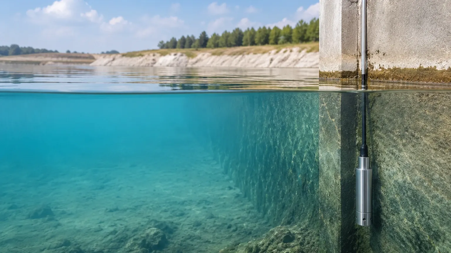
Often referred to as "throw-in" sensors, these units are designed to be lowered directly into the liquid. The sensor housing is hermetically sealed, typically made of 316L stainless steel or specialized plastics like PVDF for corrosive media. They are ideal for deep wells, reservoirs, open tanks, and lift stations where top-down access is the only option.
2. Externally Mounted Transmitters
These sensors are installed on the outside of a tank or vessel, usually at the lowest possible point. They connect via a threaded or flanged process connection. This type is preferred for closed industrial tanks where the sensor must be isolated from the internal environment for maintenance or where the liquid is agitated, which might damage a suspended submersible cable.
Technical Selection Criteria
Selecting the correct hydrostatic water level sensor requires a detailed understanding of the process environment. Engineers must evaluate several factors to ensure long-term reliability and accuracy.
* Measurement Range: The sensor must be rated for the maximum expected depth. Common ranges vary from 0–1 meter (approx. 3.28 ft) to 0–200 meters (approx. 656 ft) or more. Selecting a range too close to the maximum can lead to overpressure damage, while a range too large may reduce resolution.
* Media Compatibility: While standard water applications utilize stainless steel, wastewater or chemical processing may require specialized materials. For example, brackish water may necessitate Hastelloy or titanium diaphragms, while acidic solutions require PTFE or PVC coatings.
* Output Signals: Most industrial systems utilize a 4-20mA analog signal due to its resistance to electrical noise over long distances. However, digital protocols like RS485 (Modbus RTU) are increasingly common for smart city and IoT applications where multiple sensors are networked together.
* Accuracy Requirements: Standard industrial sensors offer accuracy levels between 0.25% and 0.5% of the Full Scale (FS). For high-precision laboratory or custody transfer applications, high-accuracy versions (0.1% FS) are available.
Practical Selection Table
| Application Type | Recommended Sensor Design | Material Consideration | Common Output |
| :— | :— | :— | :— |
| Deep Groundwater Well | Submersible (Slim-line) | Stainless Steel 316L | 4-20mA / RS485 |
| Wastewater Lift Station | Submersible (Clog-resistant) | PUR/PE Cable, Large Diaphragm | 4-20mA |
| Chemical Storage Tank | External (Flanged) | PTFE / Ceramic Diaphragm | 4-20mA + HART |
| Potable Water Reservoir | Submersible | Food-grade Stainless Steel | 4-20mA |
| Coastal/Brackish Water | Submersible | Titanium / Hastelloy | RS485 |
Installation Considerations
Proper installation is critical to the longevity of a hydrostatic water level sensor. Failure to follow engineering best practices often results in premature sensor failure or erratic readings.
1. Avoiding Turbulence: In tanks with agitators or high-flow inlet pipes, the sensor should be installed away from the direct path of the liquid flow. Turbulence can cause the sensor to swing, leading to mechanical wear on the cable and "noise" in the pressure data. In such cases, the use of a stilling well (a perforated pipe) is recommended to provide a calm environment for the sensor.
2. Cable Management: For submersible sensors, the cable serves as both the electrical conduit and the mechanical support. It should be secured with a proper cable clamp to prevent the weight of the cable from straining the internal wiring. The vented tube inside the cable must never be kinked or blocked.
3. Moisture Protection: The end of the vented cable (where it connects to the junction box) must be protected from moisture. If water enters the vent tube, it can migrate down to the electronics or create a "water plug" that interferes with atmospheric compensation. Using a junction box with a desiccant or a specialized breathable membrane is essential.
4. Lightning and Surge Protection: Because these sensors are often used in outdoor environments or deep wells, they are susceptible to induced surges from lightning. Utilizing sensors with built-in surge protection and ensuring the system is properly grounded is a standard requirement for industrial installations.
Limitations and Common Risks
While hydrostatic sensors are highly versatile, they are not suitable for every application. Engineers should be aware of the following limitations:
* Density Fluctuations: Since the sensor measures weight, any change in the liquid's density will change the level reading. For example, if the temperature of water increases significantly, its density decreases, and the sensor will report a lower level even if the actual height remains the same. If the density is variable, a different technology (like radar) or a density-compensated system should be used.
* Sediment and Build-up: In wastewater applications, sludge or debris can accumulate on the sensor diaphragm. This build-up adds weight or prevents the diaphragm from moving freely, leading to inaccurate data. Regular cleaning or the use of flush-diaphragm designs can mitigate this.
* Pressurized Vessels: A standard hydrostatic sensor cannot be used in a pressurized tank unless a differential pressure transmitter is employed. In a pressurized tank, the sensor would measure both the liquid height and the gas pressure above the liquid, resulting in a false reading.
Comparison with Alternative Technologies
When evaluating a hydrostatic water level sensor against non-contact methods like ultrasonic or radar, the choice often comes down to the specific environment.
* Hydrostatic vs. Ultrasonic: Ultrasonic sensors can be affected by foam, heavy vapor, or tank internal structures (like ladders). Hydrostatic sensors are immune to surface foam and vapor but require contact with the liquid.
* Hydrostatic vs. Radar: Radar is highly accurate and non-contact, making it ideal for extremely corrosive or high-temperature media. However, hydrostatic sensors are generally more cost-effective and are significantly easier to install in deep, narrow wells where radar signals might suffer from interference from the well walls.
For a detailed comparison of technical specifications and to explore specific models, engineers can consult the Main Page of Welk's industrial catalog for further guidance.
Frequently Asked Questions (FAQs)
Q: How often should a hydrostatic water level sensor be calibrated?
A: For most industrial applications, an annual calibration check is sufficient. However, in critical safety applications or environments with high sediment, semi-annual inspections are recommended to ensure the diaphragm is clean and the zero-point has not shifted.
Q: Can the cable of a submersible sensor be shortened?
A: Yes, most cables can be shortened, but it must be done carefully to ensure the internal vent tube is not sealed or damaged. It is often better to coil the excess cable at the top of the installation rather than cutting it, provided the vent remains clear.
Q: What is the maximum depth a hydrostatic sensor can measure?
A: Standard industrial models can typically reach depths of 200 to 500 meters. The limitation is usually the mechanical strength of the cable and the pressure rating of the sensing element.
Q: Does the sensor work in moving water, such as a river?
A: Yes, but the sensor must be protected from the direct force of the current, which can create a "dynamic pressure" error. Placing the sensor inside a stilling well or a protective pipe with small holes is the standard solution for river or stream monitoring.
Conclusion
The hydrostatic water level sensor remains a cornerstone of industrial level measurement due to its straightforward physics and adaptable design. By understanding the relationship between pressure and depth, and by following rigorous installation standards, operators can achieve precise and reliable level monitoring in even the most challenging environments. For complex applications involving high temperatures or pressurized vessels, consulting with a technical specialist is recommended to ensure the selected instrumentation aligns with the specific process requirements.