Iil Calibration Services Metalsa
Iil Calibration Services Metalsa
In the high-precision world of automotive structural components manufacturing, such as the operations managed by Metalsa, the accuracy of industrial instrumentation is not merely a preference but a regulatory and operational necessity. Level measurement instruments play a critical role in various stages of production, from chemical storage for coating processes to wastewater treatment and cooling system management. To maintain the integrity of these systems, specialized calibration protocols, often facilitated through IIL calibration services, are required to ensure that every sensor performs within its specified tolerance.
This guide explores the intersection of high-end level measurement technology and the rigorous calibration standards required in industrial environments, providing a technical roadmap for selecting, installing, and maintaining level sensors that meet the demanding criteria of global manufacturing leaders.
Measurement Principles of Industrial Level Sensors
Before implementing a calibration schedule with a provider like IIL, it is essential to understand the underlying physics of the instruments being serviced. Different technologies respond differently to environmental variables, which directly impacts how they are calibrated and verified.
Radar Level Measurement (Non-Contact)
Radar level meters utilize high-frequency electromagnetic waves (typically in the 26GHz or 80GHz range). The device emits a signal that travels to the surface of the medium, reflects, and returns to the sensor. The distance is calculated using the Time-of-Flight (ToF) principle. Because radar waves are unaffected by air temperature, pressure, or vacuum conditions, they are preferred for volatile chemical tanks where accuracy is paramount.
Ultrasonic Level Sensors
Ultrasonic sensors function similarly to radar but use sound waves instead of electromagnetic pulses. A transducer emits an ultrasonic pulse that bounces off the liquid surface. The time taken for the echo to return is proportional to the distance. However, because the speed of sound is influenced by air density and temperature, these sensors require integrated temperature compensation. They are highly effective for water treatment and open-channel flow applications within industrial facilities.
Hydrostatic Level Transmitters
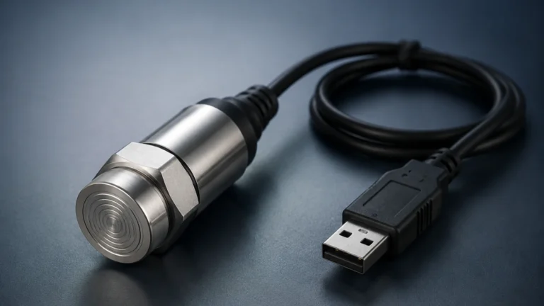
Hydrostatic measurement relies on the principle that the pressure at the bottom of a liquid column is directly proportional to the height of that liquid. By measuring the head pressure of the liquid, the transmitter converts this value into a level reading. This method is exceptionally reliable for vented tanks and deep wells, though it requires precise knowledge of the fluid's specific gravity to maintain accuracy.
Magnetic Level Gauges
Magnetic gauges use a float containing a permanent magnet that moves with the liquid level in a bypass chamber. As the float rises or falls, it flips magnetic flaps or triggers reed switches. This provides a clear visual indication and can be paired with a transmitter for remote monitoring. These are ideal for high-pressure or high-temperature applications where electronic sensors might face environmental limitations.
The Role of Calibration in Industrial Process Control
For an organization like Metalsa, calibration is the process of comparing the readings of a level instrument against a known reference standard. IIL calibration services provide the traceability required to ensure that instruments are performing according to ISO/IEC 17025 standards.
Calibration addresses several critical factors:
1. Drift Correction: Over time, electronic components can experience "drift," where the output signal slowly deviates from the actual physical level. Regular calibration resets these parameters.
2. Compliance and Quality Assurance: In automotive manufacturing, adhering to IATF 16949 standards requires documented proof that all measurement equipment is accurate.
3. Safety: In tanks containing hazardous chemicals or high-pressure steam, an inaccurate level reading can lead to overflows or dry-run conditions, posing significant safety risks.
When utilizing IIL calibration services for Metalsa facilities, the focus is often on verifying the full scale of the instrument (typically at 0%, 25%, 50%, 75%, and 100% of the range) to ensure linearity across the entire operating window.
Practical Selection Table for Level Measurement
Choosing the right instrument is the first step toward a stable, easily calibrated system. The following table compares common technologies used in industrial automation.
| Technology | Typical Accuracy | Max Range | Medium Type | Key Advantage |
| :— | :— | :— | :— | :— |
| Radar (80GHz) | ±1 mm | 30 m – 120 m | Liquids/Solids | Non-contact, unaffected by vapor |
| Ultrasonic | ±0.25% of range | 15 m | Water/Chemicals | Cost-effective for simple liquids |
| Hydrostatic | ±0.1% to 0.5% | 200 m | Clean Liquids | Simple installation, very stable |
| Magnetic Gauge | ±5 mm | 6 m (standard) | Corrosive/High Temp | Visual local indication, no power required |
| Level Switches | N/A (Point level) | N/A | Various | Redundant overfill protection |
For a comprehensive look at the latest hardware options tailored for these applications, engineers can Review product options and application support to align their hardware selection with their specific calibration requirements.
Installation Considerations for Calibrated Systems
Even the most precisely calibrated instrument will provide inaccurate data if installed incorrectly. Proper physical placement is the foundation of measurement integrity.
Obstructions and Dead Zones
Every sensor has a "dead zone" or "blocking distance" near the transducer where measurements cannot be taken. For ultrasonic and radar sensors, this is typically between 0.1 m and 0.5 m. The sensor must be mounted high enough that the maximum liquid level never enters this zone. Furthermore, internal tank structures like ladders, agitators, or heating coils can create false echoes. Advanced radar meters use "false echo suppression" software, but physical clearance is always the best practice.
Mounting Orientation
For hydrostatic transmitters, the sensor must be submerged at a fixed point where it will not be moved by turbulence or agitator flow. For radar and ultrasonic sensors, the transducer face must be perfectly parallel to the liquid surface. A deviation of just a few degrees can significantly weaken the return signal, leading to intermittent signal loss.
Environmental Protection
In heavy industrial environments, sensors are exposed to dust, moisture, and vibration. Using instruments with high IP ratings (IP67 or IP68) and ensuring that cable glands are properly sealed is vital. When IIL calibration services are performed on-site at Metalsa, the technician will often inspect these physical conditions as part of the validation process.

Limitations and Challenges in Level Measurement
While modern instrumentation is highly advanced, certain physical conditions present challenges that cannot always be solved by calibration alone.
* Foam and Turbulence: Thick foam can absorb ultrasonic and radar signals, leading to "lost echo" errors. In these cases, a stilling well or a contact-based technology like a magnetic level gauge may be necessary.
* Dielectric Constant (Dk): Radar measurement depends on the dielectric constant of the medium. Materials with a very low Dk (like certain oils or liquefied gases) reflect less energy. If the Dk is too low, the radar may "see through" the liquid to the tank bottom.
* Vapor and Vacuum: While radar handles vacuum well, ultrasonic waves require a medium (air/gas) to travel. In high-vacuum tanks, ultrasonic sensors will fail completely.
* Specific Gravity Fluctuations: Hydrostatic sensors assume a constant fluid density. If the temperature of the fluid changes significantly, or if different chemicals are mixed, the density changes, and the level reading will become inaccurate despite the sensor being perfectly calibrated.
Maintenance and Re-calibration Cycles
The frequency of calibration depends on the criticality of the process. For Metalsa’s core production lines, an annual calibration cycle is standard. However, for systems involving safety-instrumented functions (SIF), semi-annual checks may be required.
Maintenance checklists should include:
* Cleaning the transducer face of any buildup or condensation.
* Checking the integrity of the pressure diaphragm in hydrostatic sensors.
* Verifying the movement of the float in magnetic gauges.
* Reviewing the diagnostic logs of digital transmitters for any signal strength warnings.
Frequently Asked Questions (FAQs)
Q: How does IIL calibration services ensure traceability for Metalsa?
A: Traceability is established by using reference standards that are themselves calibrated against national or international standards (such as NIST). Each calibration event results in a certificate that documents the uncertainty and the specific equipment used, creating a continuous chain of verification.
Q: Can I calibrate a level meter while the tank is in operation?
A: Some "dry calibration" methods allow for electronic verification of the transmitter's circuitry. However, a true "wet calibration" requires changing the actual level in the tank or using a portable calibration column to verify the sensor's response to the physical medium.
Q: What is the difference between a level transmitter and a level switch?
A: A level transmitter provides continuous measurement (e.g., 4-20mA or Modbus signal representing 0-100%), whereas a level switch provides a point-level alert (e.g., a relay contact) when the liquid reaches a specific height. Switches are often used as redundant safety backups for transmitters.
Q: Why is 80GHz radar becoming the standard for industrial level measurement?
A: The higher frequency allows for a narrower beam angle, which makes it easier to avoid internal tank obstructions and provides better resolution, even in small tanks or through narrow nozzles.
By integrating robust level measurement hardware with professional IIL calibration services, Metalsa and similar industrial entities can ensure their processes remain efficient, compliant, and safe. Selecting the right technology based on measurement principles and environmental factors is the first step in building a reliable industrial control system.