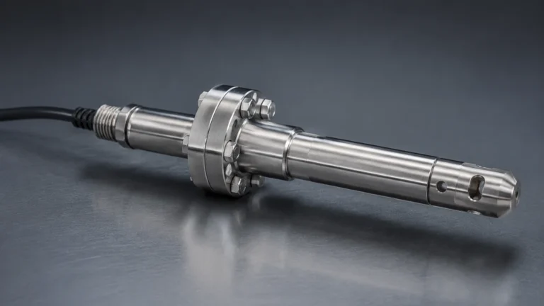
Im41
Im41
In the field of industrial automation and process control, the accuracy of level measurement is paramount to operational safety and efficiency. The IM41 designation frequently refers to a specific class of high-frequency radar level measurement modules and signal processing units integrated into advanced radar level transmitters. These components are engineered to handle complex signal environments, providing the computational power necessary to distinguish between true material levels and false echoes caused by tank internal structures.
This guide examines the technical architecture of IM41-based systems, their underlying measurement principles, and the practical considerations required for successful deployment in industrial environments. Whether managing liquid chemicals or bulk solids, understanding the nuances of this technology is essential for instrumentation engineers and plant managers.
Understanding the Measurement Principle of IM41 Radar Modules
The IM41 module typically operates on the principle of high-frequency pulse radar, often utilizing the 26GHz or 80GHz frequency bands. Unlike older ultrasonic technologies that rely on sound waves, radar uses electromagnetic pulses that travel at the speed of light. This allows for measurements that are virtually unaffected by changes in temperature, pressure, or the presence of vacuum conditions.
The Time-of-Flight (ToF) Method
The core function of the IM41 module is to manage the Time-of-Flight (ToF) calculation. The process follows a specific sequence:
1. Emission: The radar antenna emits a short microwave pulse directed toward the medium surface.
2. Reflection: The pulse reaches the surface of the medium (liquid or solid) and is reflected back toward the sensor. The strength of this reflection is determined by the dielectric constant (εr) of the material.
3. Reception: The antenna receives the reflected signal.
4. Processing: The IM41 module calculates the time interval between emission and reception.
The distance ($D$) from the sensor reference point to the material surface is calculated using the formula:
$D = (c \times t) / 2$
Where $c$ is the speed of light and $t$ is the measured time. The module then subtracts this distance from the total tank height to determine the level of the material.
Advanced Signal Processing
What distinguishes the IM41 from basic level sensors is its digital signal processing (DSP) capability. Industrial tanks are rarely empty voids; they contain agitators, heating coils, ladders, and support beams. The IM41 module utilizes "Echo Tracking" and "False Echo Suppression" algorithms. By mapping the empty tank profile, the module can identify and ignore static reflections from internal obstructions, focusing only on the dynamic signal returned from the material surface.
Key Technical Specifications and Performance Metrics
When evaluating IM41-integrated sensors, technical specifications must be aligned with the specific requirements of the process vessel. The following parameters define the operational boundaries of the technology:
* Frequency Range: Typically 26GHz. Higher frequencies allow for smaller antenna sizes and narrower beam angles, which are critical for avoiding tank walls and internal obstacles.
* Measuring Range: Standard modules support ranges from 0.3 meters (the typical blind zone) up to 30 meters for liquids and 70 meters for certain solid applications.
* Measurement Accuracy: High-precision IM41 units offer accuracy within ±2mm to ±5mm, depending on the dielectric properties of the medium and the stability of the surface.
* Beam Angle: Depending on the antenna type (horn, parabolic, or rod), the beam angle usually ranges between 8° and 12°. A narrower beam ensures that the energy is concentrated on the target, reducing noise.
* Output Signals: Standard integration includes 4-20mA analog outputs with HART protocol, or digital communication via RS485 (Modbus).
Application Scenarios for IM41-Based Level Sensors
Due to the non-contact nature and high-frequency stability of the IM41 module, it is suitable for a wide range of demanding industries.
Chemical and Petrochemical Processing
In chemical storage, media are often corrosive or volatile. IM41 radar sensors can be equipped with PTFE (Polytetrafluoroethylene) or specialized alloy antennas to resist chemical attack. Because the sensor does not touch the medium, maintenance requirements are significantly lower than with contact-based methods like float switches or guided wave radar.
Water and Wastewater Treatment
In large-scale water treatment plants, IM41 technology is used for monitoring open channels, reservoirs, and chemical dosing tanks. The ability to measure accurately through steam or light foam makes it superior to ultrasonic sensors, which often fail in high-humidity or high-temperature environments.
Bulk Solids and Silos
Measuring the level of powders, grains, or minerals presents challenges such as dust and uneven surface profiles (cones of repose). The IM41 module’s high-frequency pulses can penetrate moderate dust clouds, while the narrow beam angle prevents interference from the silo walls, which is a common issue in tall, narrow structures.
Selection Criteria for Industrial Level Measurement
Choosing the correct configuration for an IM41-based instrument requires a systematic evaluation of the process environment. The table below provides a general framework for selection:
| Criteria | Liquid Applications | Solid Applications | Considerations |
| :— | :— | :— | :— |
| Dielectric Constant (εr) | High (Water-based) to Low (Oils) | Usually Low (Grains, Powders) | Low εr requires more sensitive signal processing. |
| Surface Condition | Calm, Turbulent, or Foaming | Dusty, Uneven, or Sloping | Turbulent liquids or sloping solids reduce signal return. |
| Process Pressure | Vacuum to 4.0 MPa | Usually Atmospheric | High pressure requires specialized flange seals. |
| Process Temperature | -40°C to +250°C | -40°C to +150°C | High temperatures may require cooling fins or stand-offs. |
| Tank Geometry | Narrow or Wide | Tall and Narrow (Silos) | Beam angle must be smaller than the clearance to the wall. |
For a detailed breakdown of specific hardware models and their compatibility with various industrial protocols, engineers should visit the Main Page to review technical documentation and application-specific support.

Installation Guidelines and Best Practices
The performance of an IM41 radar level meter is heavily dependent on correct installation. Even the most advanced signal processing cannot compensate for a poorly positioned sensor.
1. Positioning and Clearance
The sensor should ideally be installed at 1/4 to 1/6 of the tank diameter away from the tank wall. Installing the sensor too close to the wall will result in parasitic reflections that can interfere with the true level signal. Conversely, installing it directly in the center of a domed-roof tank can cause multi-path interference where the signal bounces multiple times between the roof and the surface.
2. Avoiding Obstructions
The "signal path" or the cone of the radar beam must be kept clear of internal obstructions. This includes:
* Inlet streams (never install the sensor directly above the filling point).
* Agitator blades (if unavoidable, the IM41’s false echo suppression must be calibrated while the agitator is moving).
* Ladders and support struts.
3. Nozzle Design
The length and diameter of the mounting nozzle are critical. If the nozzle is too long or too narrow, the radar pulse may reflect off the internal edge of the nozzle before it even enters the tank. Ideally, the antenna should extend slightly beyond the bottom of the nozzle to ensure a clean launch of the microwave pulse.
Limitations and Operational Constraints
While IM41-based radar is highly versatile, it is not a universal solution for every process. Engineers must be aware of the following limitations:
* Heavy Foam: While radar can penetrate light foam, extremely thick or dense foam (especially foam with high conductivity) can absorb the radar signal entirely, leading to a "loss of echo" error.
* Extremely Low Dielectric Media: Materials with a dielectric constant below 1.4 (such as certain liquefied gases) provide very weak reflections. In these cases, guided wave radar or specialized high-sensitivity IM41 modules are required.
* The Blind Zone: Every radar sensor has a minimum distance (dead band) near the antenna where measurement is not possible. For IM41 modules, this is typically between 200mm and 400mm. The sensor must be mounted high enough to ensure the maximum liquid level does not enter this zone.
Frequently Asked Questions (FAQs)
Q: Can the IM41 module be used in explosive atmospheres?
A: Yes, most transmitters utilizing the IM41 module are designed for hazardous areas and carry certifications such as ATEX, IECEx, or Ex ia (intrinsically safe) and Ex d (flameproof). Always verify the specific rating on the device nameplate.
Q: How does dust affect the IM41 radar signal?
A: Unlike ultrasonic sensors, which are easily blocked by dust, 26GHz radar pulses can penetrate moderate to heavy dust. However, in extremely dense pneumatic conveying applications, signal attenuation may occur, necessitating a higher-power 80GHz module or a purging system to keep the antenna face clean.
Q: Is periodic recalibration necessary?
A: Because radar is a time-based measurement and does not rely on mechanical moving parts, it is highly stable. Recalibration is usually only necessary if the tank geometry changes or if the module is moved to a different application with significantly different dielectric properties.
Q: What is the benefit of the HART protocol in these modules?
A: The HART protocol allows for digital communication over the existing 4-20mA wiring. This enables technicians to perform remote diagnostics, adjust false echo suppression maps, and update configuration parameters without opening the sensor housing in the field.
Conclusion
The IM41 represents a sophisticated approach to level measurement, combining the physical advantages of high-frequency radar with robust digital signal processing. By understanding the relationship between frequency, beam angle, and the dielectric properties of the medium, process engineers can implement reliable level monitoring solutions even in the most challenging industrial environments. For further technical specifications, installation drawings, and product comparisons, please refer to the Main Page for comprehensive engineering resources.