Impact Flow Meter
Impact Flow Meter
In the processing of bulk solids, accurate mass flow measurement is essential for inventory management, process control, and quality assurance. Among the various technologies available for measuring the flow of dry, granular, or powdered materials, the impact flow meter stands out as a robust and reliable mechanical-electronic solution. Unlike belt scales that require significant horizontal space or Coriolis meters for solids which can be complex to maintain, the impact flow meter utilizes the kinetic energy of falling material to determine mass flow rates in real-time.
This guide provides a comprehensive technical overview of impact flow measurement, detailing the underlying physics, selection criteria, and installation best practices for industrial engineers and plant managers. For more information on integrated measurement systems, you can visit the Main Page of Welk's industrial instrumentation suite.
Measurement Principles of the Impact Flow Meter
The operation of an impact flow meter is based on the principle of the impulse-momentum change. When a bulk solid material falls from a controlled height and strikes a sensing plate inclined at a specific angle, it exerts a force on that plate. This force is proportional to the mass flow rate of the material.
The Physics of Impact
According to Newton’s Second Law of Motion, the force exerted by the material is equal to the rate of change of momentum. In an impact flow meter, the material is typically fed into the device so that it falls vertically under gravity. As it hits the sensing plate, the material is deflected.
The total force exerted on the plate can be decomposed into two vectors: a vertical component and a horizontal component. Most modern impact flow meters are designed to measure only the horizontal force component. This is a critical design choice because the horizontal force is independent of the weight of any material that might temporarily accumulate or "build up" on the sensing plate. By isolating the horizontal force, the meter maintains accuracy even when handling sticky or dusty materials that would otherwise cause zero-drift in a system measuring total weight.
Mathematical Representation
The relationship can be simplified as:
F = Q × v × sin(θ)
Where:
* F is the horizontal force measured by the sensor.
* Q is the mass flow rate (e.g., kg/h).
* v is the velocity of the material at the point of impact.
* θ is the angle of the sensing plate relative to the vertical path.
Since the drop height is constant, the velocity (v) remains constant, and the angle (θ) is fixed by the mechanical design. Therefore, the force (F) becomes directly proportional to the mass flow rate (Q).
Key Components and Construction
To ensure long-term reliability in harsh industrial environments, the construction of an impact flow meter must be robust. The system generally consists of the following components:
1. The Sensing Plate: Often referred to as the impact plate, this is the primary sensing element. It is typically manufactured from stainless steel or specialized alloys. For abrasive materials like sand or ores, the plate may be coated with ceramic, tungsten carbide, or polyurethane to prevent wear.
2. The Transducer (Load Cell or LVDT): This component converts the mechanical force into an electrical signal. High-precision strain gauge load cells or Linear Variable Differential Transformers (LVDT) are used to detect the minute displacements of the sensing plate.
3. The Housing: A dust-tight and often pressure-resistant enclosure that protects the sensing mechanism and contains the material flow. In food-grade or chemical applications, the housing is usually 304 or 316 stainless steel.
4. Damping Mechanism: To prevent mechanical noise and vibration from interfering with the measurement, many meters include oil-filled dampers or electronic filtering to stabilize the signal.
5. Electronics and Integration: The transmitter processes the raw signal, performs temperature compensation, and provides outputs such as 4-20mA, Modbus, or Profibus. This allows the meter to communicate with the Main Page of the plant's PLC or SCADA system.
Selection Criteria for Industrial Applications
Choosing the right impact flow meter requires a thorough understanding of the material characteristics and the process environment. The following table outlines the primary considerations for selection:
| Parameter | Requirement/Consideration |
| :— | :— |
| Flow Rate Range | Ensure the meter is sized for 20% to 100% of the maximum expected flow (e.g., 500 kg/h to 100,000 kg/h). |
| Particle Size | Typically suitable for particles from 10 microns up to 25 mm (1 inch). Large clumps can cause signal spikes. |
| Material Temperature | Standard units handle up to 80°C (176°F); high-temp versions can exceed 250°C (482°F). |
| Bulk Density | Consistent density is preferred, though the impact principle is less sensitive to density changes than volumetric meters. |
| Abrasiveness | Highly abrasive materials require hardened or replaceable sensing plates. |
| Moisture Content | Materials should be free-flowing. High moisture (>5%) can lead to sticking and inconsistent trajectories. |
Material Compatibility
Impact flow meters are ideal for materials such as cement, fly ash, plastic pellets, grain, coal dust, and various chemicals. However, they are not recommended for materials that are extremely fibrous or those that exhibit "slugging" behavior, where the material falls in large, inconsistent masses rather than a continuous stream.
Installation and Engineering Considerations
The accuracy of an impact flow meter is heavily dependent on how the material is delivered to the sensing plate. If the material does not hit the plate at a consistent velocity and angle, the measurement will be unreliable.
1. The Feed System
Material should be fed to the meter using a device that ensures a constant flow, such as a rotary valve, screw conveyor, or vibratory feeder. A "dead box" or a pre-feed chute is often used to dissipate the kinetic energy of the material from the conveyor before it enters the meter’s inlet, ensuring it falls purely under the influence of gravity from a fixed height.
2. Drop Height
A minimum drop height (typically 300 mm to 500 mm / 12 to 20 inches) is required to ensure the material reaches a stable velocity. If the drop height is too short, the signal-to-noise ratio will be poor. If it is too high, the impact force may exceed the load cell's capacity or cause excessive wear on the plate.
3. Vibration Isolation
Because the meter measures small mechanical forces, external vibrations from nearby crushers, fans, or conveyors can introduce errors. The meter should be installed using flexible connections at the inlet and outlet, and the mounting structure should be rigid and isolated from high-vibration equipment.
4. Venting and Dust Control
In closed systems, air pressure differentials can exert forces on the sensing plate. Proper venting or the use of a pressure-compensation line is necessary to ensure that the meter only measures the force of the material impact, not the air pressure.
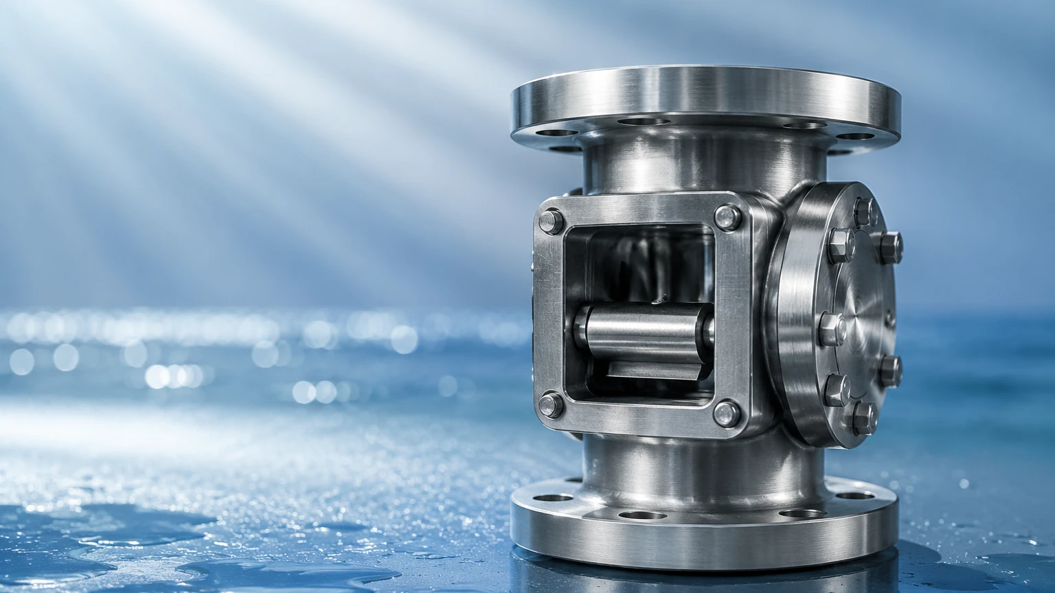
Comparison with Other Solids Flow Measurement Technologies
Engineers often weigh the impact flow meter against other technologies. Understanding the trade-offs is essential for optimal process design.
* Belt Scales: Belt scales are excellent for long-distance transport but require significant floor space and are sensitive to belt tension and alignment. Impact meters are much more compact and easier to retrofit into existing vertical gravity chutes.
* Coriolis Solids Flow Meters: These offer higher accuracy (often ±0.5%) but are significantly more expensive and have higher maintenance requirements due to the rotating sensing elements. Impact meters typically offer ±1.0% to ±2.0% accuracy, which is sufficient for most process control applications.
* Microwave Flow Meters: These are non-intrusive and measure flow through a pipe wall. However, they are highly sensitive to changes in moisture and particle size distribution. The impact flow meter provides a more direct mechanical measurement of mass.
Limitations and Operational Risks
While highly versatile, the impact flow meter is not a "fit and forget" solution. Certain risks must be managed:
* Material Buildup: Although horizontal force measurement mitigates the effect of buildup, extreme accumulation can change the effective shape or angle of the sensing plate, altering the flow trajectory. Periodic inspection is required for sticky materials.
* Zero Drift: Dust accumulation on the internal mechanical linkages can cause the zero point to shift. Regular "zeroing" of the instrument (when the flow is stopped) is a standard maintenance task.
* Mechanical Wear: In high-velocity or abrasive applications, the sensing plate will eventually wear down. A worn plate changes the impact dynamics and reduces accuracy. Using a Main Page resource to identify the correct wear-resistant coatings can extend the service life of these components.
Frequently Asked Questions (FAQ)
Q: Can an impact flow meter be used for liquids?
A: No. Impact flow meters are specifically designed for bulk solids. For liquid flow measurement, technologies like electromagnetic, ultrasonic, or turbine flow meters are appropriate.
Q: How often should the meter be calibrated?
A: Initial calibration is performed using a known weight of material passed through the system (static or dynamic calibration). After the initial setup, we recommend a calibration check every 6 to 12 months, depending on the abrasiveness of the material and the criticality of the measurement.
Q: What is the maximum particle size an impact flow meter can handle?
A: Most standard industrial units can handle particles up to 25 mm (approx. 1 inch). For larger rocks or ore, specialized heavy-duty impact plates and reinforced housings are required to prevent mechanical damage.
Q: Does the color or chemical composition of the material affect the reading?
A: No. The measurement is purely mechanical, based on mass and velocity. Unlike optical or microwave sensors, the impact flow meter is unaffected by the color, dielectric constant, or chemical makeup of the solid, provided the physical flow characteristics remain consistent.
Q: How does the meter handle pulsating flow?
A: Pulsating flow (common with rotary valves) can cause the output signal to fluctuate. This is typically managed through electronic damping or averaging in the transmitter's software to provide a stable reading for the control system.
By following these engineering guidelines and ensuring proper installation, the impact flow meter serves as a highly effective tool for managing bulk solid processes. For further technical specifications on level and flow instrumentation, consult the professional resources available at the Welk Main Page.