Impeller Flow Sensor
Impeller Flow Sensor
In the landscape of industrial fluid management, the impeller flow sensor—often referred to as a paddlewheel sensor—represents one of the most reliable and cost-effective methods for measuring the velocity of liquids in closed pipe systems. Designed for a wide range of applications from water treatment to chemical processing, these sensors provide essential data for process control, batching, and monitoring. This guide examines the technical principles, selection criteria, and installation requirements for impeller flow sensors, while highlighting how they complement broader measurement strategies in industrial automation.
Principles of Impeller Flow Measurement
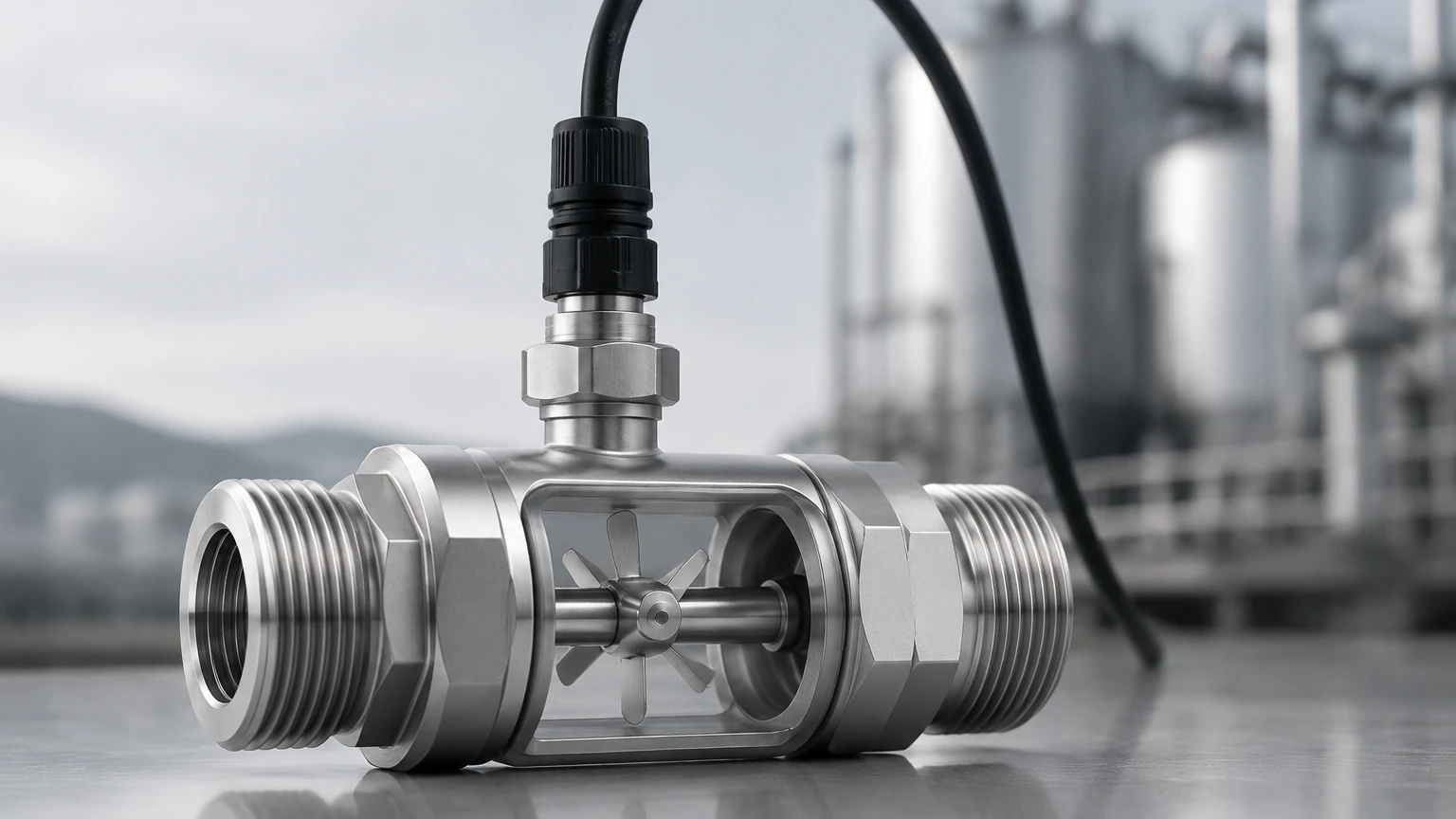
The operation of an impeller flow sensor is based on the conversion of the kinetic energy of a moving fluid into mechanical rotation. As liquid flows through a pipe, it makes contact with the blades of an impeller or paddlewheel positioned in the flow stream. The rotational speed of this impeller is directly proportional to the linear velocity of the fluid.
The Transduction Process
To convert this mechanical rotation into a usable electrical signal, most industrial impeller sensors utilize one of two primary methods:
1. Hall Effect Sensors: Small magnets are embedded within the tips of the impeller blades. As the blades rotate past a sensor located in the housing, a frequency signal (pulse) is generated. This method is highly reliable and provides a digital output that is easily interpreted by PLCs (Programmable Logic Controllers).
2. Inductive Sensors: These sensors detect the passage of metal-laden or metallic blades without the need for magnets. This is often preferred in applications where magnetic particles in the fluid might otherwise cling to the impeller and cause interference.
The K-Factor
The relationship between the pulse frequency and the volumetric flow rate is defined by the "K-factor." This value represents the number of pulses generated per unit of volume (e.g., pulses per liter or pulses per gallon). Because the flow profile within a pipe is not perfectly uniform, the K-factor is specific to the pipe diameter, material, and the internal roughness of the system. Accurate calibration is essential to ensure the sensor provides a true representation of the flow rate.
Key Technical Evaluation Criteria
Selecting the correct impeller flow sensor requires a detailed understanding of the process environment. Engineers must evaluate several factors to ensure longevity and accuracy.
Fluid Compatibility and Material Selection
The chemical composition of the fluid dictates the materials used for the sensor body, the impeller, the shaft, and the O-rings. Common materials include:
* Polypropylene (PP): Suitable for general water use and many mild chemicals.
* Polyvinylidene Fluoride (PVDF): Highly resistant to aggressive chemicals and acids.
* Stainless Steel (316L): Used for high-pressure applications or where mechanical durability is paramount.
* Ceramic or Tungsten Carbide: Often used for the shaft and bearings to minimize wear in high-cycle applications.
Flow Range and Pipe Size
Impeller sensors are velocity-dependent. They typically require a minimum flow velocity (often around 0.3 meters per second or 1 foot per second) to overcome the initial friction of the bearings and begin rotating. Conversely, excessively high velocities can lead to premature bearing wear or cavitation. Most industrial units are designed for pipe sizes ranging from DN15 (1/2 inch) to DN900 (36 inches) or larger, depending on whether they are inline or insertion-style designs.
Pressure and Temperature Ratings
Standard plastic sensors are often rated for pressures up to 10 bar (145 psi) at ambient temperatures, but their pressure-bearing capacity drops significantly as the temperature increases. Metal-bodied sensors can handle much higher pressures, often exceeding 50 bar (725 psi), and temperatures up to 120°C (248°F) or higher.
Selection Table for Industrial Applications
| Parameter | Requirement | Typical Specification |
| :— | :— | :— |
| Fluid Type | Clean, low-viscosity liquids | < 1% solids, < 100 cP viscosity |
| Velocity Range | 0.3 to 6 m/s (1 to 20 fps) | Optimal accuracy between 1–5 m/s |
| Accuracy | Process monitoring | ±1% to ±5% of full scale |
| Output Signal | Integration with PLC/SCADA | 4-20mA, Pulse (NPN/PNP), or Modbus |
| Installation Type | Pipe diameter dependent | Inline (small pipes) / Insertion (large pipes) |
| Maintenance | Accessible location | Periodic bearing inspection required |
Engineering and Installation Guidelines
The accuracy of an impeller flow sensor is heavily influenced by the flow profile of the liquid. For the sensor to provide a stable reading, the fluid must be in a "fully developed" turbulent flow state, free from swirls or pulsations.
Straight Pipe Requirements
To achieve a stable flow profile, sensors must be installed with specific lengths of straight pipe both upstream and downstream. The standard rule of thumb is:
* Upstream: 10 times the pipe diameter (10D).
* Downstream: 5 times the pipe diameter (5D).
If the installation follows a pump, a partially closed valve, or a 90-degree elbow, the upstream requirement may increase to 20D or 50D to allow turbulence to subside.
Sensor Orientation
In horizontal pipe runs, the sensor should ideally be mounted at the 12 o'clock (top) or 3/9 o'clock (side) positions. Mounting at the 6 o'clock (bottom) position is discouraged, as sediment and debris can accumulate in the sensor housing, leading to mechanical failure or clogging. In vertical pipes, the flow should always be upward to ensure the pipe remains completely full of liquid, preventing air pockets that would cause erratic readings.
Avoiding Cavitation and Aeration
Air bubbles in the line will cause the impeller to spin at incorrect speeds, leading to significant measurement errors. Similarly, if the pressure drops too low at the sensor location, cavitation may occur, potentially damaging the impeller blades. Ensuring the system pressure remains above the vapor pressure of the liquid is a critical design consideration.
Operational Challenges and Maintenance
While impeller flow sensors are robust, they are mechanical devices subject to physical interaction with the process fluid. This introduces specific maintenance needs.
1. Bearing Wear: Over time, the shaft and bearings of the impeller will wear down. This increases friction, causing the sensor to under-read at low velocities. Regular inspection and replacement of the rotor assembly (typically every 12 to 24 months in continuous use) are recommended.
2. Particulate Accumulation: Even "clean" water systems can have scale or biological growth. If fibers or large particles catch on the impeller, they can slow it down or stop it entirely. Using a strainer upstream can mitigate this risk.
3. Viscosity Effects: Impeller sensors are calibrated for water-like viscosities. As viscosity increases (above 100 centipoise), the drag on the impeller changes, and the standard K-factor may no longer be accurate. For high-viscosity fluids, electromagnetic or Coriolis meters are often more appropriate.
Integrating Flow and Level Measurement
In many industrial processes, flow measurement does not exist in isolation. It is frequently paired with level measurement to provide a complete picture of system health and mass balance. For instance, in a chemical storage tank, an impeller flow sensor monitors the outflow while a radar or ultrasonic level transmitter monitors the remaining inventory.
By comparing the integrated flow data (totalized flow) against the change in tank level, operators can detect leaks or identify pump inefficiencies. If the level in a tank drops faster than the flow sensor indicates, it may signal a leak in the discharge piping. Conversely, if the flow sensor shows movement but the level remains static, it could indicate a sensor malfunction or a closed valve. For engineers looking to optimize these dual-measurement systems, visiting the Main Page provides a comprehensive overview of the level measurement technologies that work alongside flow sensors to ensure process safety and efficiency.
Welk’s range of level instruments, including high-frequency radar and hydrostatic transmitters, are designed to integrate seamlessly with the same control systems used for impeller flow sensors, allowing for a unified approach to industrial automation.
Frequently Asked Questions (FAQs)
Q: Can impeller flow sensors be used with deionized (DI) water?
A: Yes, provided the materials of construction are compatible. Many DI water systems use PVDF or Polypropylene sensors with ceramic shafts to maintain high purity levels and prevent metallic contamination.
Q: How do I know if my sensor is fouled?
A: A common sign of fouling is an erratic output or a "sluggish" response to changes in pump speed. If the flow rate is known to be constant but the sensor output is drifting downward, it is likely that debris is wrapped around the impeller or the bearings are failing.
Q: What is the maximum distance for the signal transmission?
A: For raw pulse signals (NPN/PNP), the distance is typically limited to 60–100 meters (200–330 feet) before signal degradation occurs. For longer distances, a 4-20mA transmitter or a digital protocol like Modbus RS485 should be used.
Q: Are these sensors suitable for steam or gas?
A: No. Impeller flow sensors are specifically designed for liquids. Gases do not have sufficient density to drive the impeller reliably at standard velocities, and the high speeds associated with gas flow would quickly destroy the bearings.
Q: How does pipe material affect the sensor?
A: The sensor itself is usually unaffected, but the installation hardware (saddles or tees) must match the pipe material (PVC, Stainless Steel, Copper, etc.) to ensure a leak-proof seal and the correct insertion depth for the impeller into the flow stream.