Clamp on Ultrasonic Flow Sensor
Clamp on Ultrasonic Flow Sensor
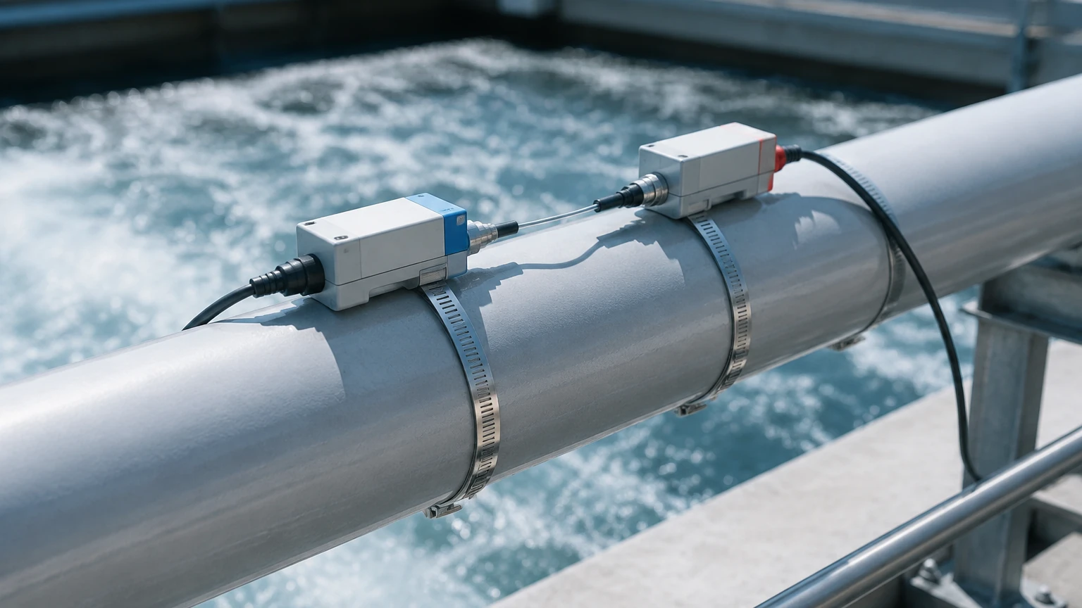
In the landscape of industrial process control, the ability to measure fluid velocity without breaching the integrity of a piping system is a significant advantage. A clamp on ultrasonic flow sensor provides a non-invasive solution for measuring the flow rate of liquids within a closed pipe. Unlike traditional inline flow meters, such as electromagnetic or turbine meters, these sensors are mounted to the exterior of the pipe. This eliminates the need for pipe cutting, process downtime, and the risk of pressure drops or leaks. For engineers managing complex systems, understanding the technical nuances of these sensors is essential for ensuring long-term accuracy and system reliability.
Understanding Ultrasonic Flow Measurement Principles
To effectively select and deploy a clamp on ultrasonic flow sensor, one must first understand the two primary physical principles used: Transit-Time and Doppler Effect. Both methods utilize ultrasonic waves—sound frequencies above the human hearing range (typically 0.5 to 4 MHz)—but they apply them differently depending on the fluid characteristics.
Transit-Time Method
Transit-time technology is the most common method for clean liquids. It relies on the principle that an ultrasonic signal travels faster when moving with the flow (downstream) than when moving against it (upstream). Two transducers are placed on the pipe, acting as both transmitters and receivers. By measuring the precise time difference (delta-t) between the upstream and downstream pulses, the sensor calculates the flow velocity.
Mathematically, the relationship is expressed as:
$$V = K \cdot \Delta t$$
Where $V$ is the flow velocity, $K$ is a constant determined by the pipe geometry and sound speed in the fluid, and $\Delta t$ is the time difference. This method is highly accurate for fluids with less than 2% total suspended solids (TSS) or aeration.
Doppler Effect Method
The Doppler method is used for "dirty" liquids or those containing entrained air bubbles. The sensor transmits an ultrasonic signal into the pipe, which reflects off particles or bubbles moving with the fluid. Because these reflectors are in motion, the frequency of the reflected signal is shifted (the Doppler shift). The frequency shift is directly proportional to the velocity of the fluid. While generally less accurate than transit-time meters, Doppler sensors are indispensable for wastewater, slurries, and aerated liquids where transit-time signals would be scattered or absorbed.
Key Evaluation Criteria for Sensor Selection
Selecting the correct clamp on ultrasonic flow sensor requires a detailed analysis of the application environment. Because the signal must pass through the pipe wall and the fluid, several variables can affect performance.
Pipe Material and Condition
The pipe must be a sonically conductive material. Common materials include carbon steel, stainless steel, ductile iron, copper, and most plastics (PVC, PE, PVDF). However, pipes with internal liners (such as cement, rubber, or glass) present a challenge. If the liner is not perfectly bonded to the outer pipe wall, an air gap may exist, which reflects the ultrasonic signal and prevents measurement. Furthermore, older pipes with significant internal scaling or heavy external corrosion may require surface preparation to ensure a clean acoustic path.
Fluid Properties
For transit-time sensors, the fluid must be relatively clean and homogeneous. The speed of sound in the fluid varies with temperature and pressure, so the sensor's signal processor must be calibrated for the specific liquid (e.g., water, glycol, oil, or chemicals). If the fluid temperature fluctuates significantly, an integrated temperature sensor may be required for real-time compensation of the sound-speed calculation.
Accuracy and Flow Profile
Most industrial clamp-on sensors offer an accuracy of ±1% to ±3% of the flow rate. To achieve this, the flow profile must be fully developed and stable. This is managed by ensuring sufficient straight pipe runs before and after the sensor location. Turbulence caused by valves, pumps, or elbows can distort the flow profile, leading to measurement errors.
Comparison of Measurement Methods and Applications
The following table provides a general guideline for choosing between transit-time and Doppler technologies based on common industrial scenarios.
| Feature | Transit-Time Sensor | Doppler Effect Sensor |
| :— | :— | :— |
| Fluid Type | Clean liquids, deionized water, oils | Slurries, wastewater, aerated fluids |
| Suspended Solids | < 2% by volume | > 100 ppm (minimum particle size > 75 microns) |
| Typical Accuracy | ±0.5% to ±2% | ±2% to ±5% |
| Pipe Sizes | DN15 to DN6000 (0.5" to 240") | DN25 to DN6000 (1" to 240") |
| Installation | Dual transducer (V, Z, or W path) | Single or dual transducer (usually adjacent) |
| Common Use Case | HVAC, chemical dosing, water utility | Mining, sewage, crude oil with sand |
Installation Best Practices and Pipe Requirements
The performance of a clamp on ultrasonic flow sensor is heavily dependent on the quality of the installation. Unlike inline meters, where the manufacturer controls the internal geometry, clamp-on meters rely on the installer to define the acoustic path accurately.
Straight Pipe Run Requirements
To ensure a laminar flow profile, the sensor should be installed on a straight section of pipe. The standard engineering guideline is "10D Upstream and 5D Downstream." This means if the pipe diameter (D) is 100 mm (4 inches), there should be 1000 mm (40 inches) of straight pipe before the sensor and 500 mm (20 inches) after it. If the sensor is placed after a pump or a modulating valve, the upstream requirement may increase to 20D or 30D.
Mounting Orientations (V, W, and Z Paths)
Depending on the pipe diameter and the signal strength, three primary mounting configurations are used:
1. V-Method: The signal bounces once off the opposite pipe wall. This is the standard for pipes ranging from DN25 to DN400 (1" to 16").
2. Z-Method: Transducers are placed on opposite sides of the pipe, and the signal passes through only once. This is used for large pipes (above DN400) or where the fluid is slightly attenuating.
3. W-Method: The signal bounces three times. This is used for very small pipes (typically under DN50) to increase the signal's travel time and improve resolution.
Coupling Compounds and Surface Prep
Air is the enemy of ultrasonic signals. To eliminate air gaps between the transducer and the pipe surface, a coupling compound (typically silicone grease or an epoxy gel) must be applied. For permanent installations, solid coupling pads or high-temperature foils may be used. The pipe surface must be sanded smooth of paint flakes, rust, or pits to ensure a continuous acoustic bond.
Limitations and Potential Risks in Industrial Environments
While highly versatile, clamp on ultrasonic flow sensors are not a universal solution. Engineers must be aware of specific limitations that can lead to "No Signal" errors or inaccurate readings.
* Acoustic Short-Circuiting: In some thick-walled metal pipes, the ultrasonic signal may travel through the pipe wall itself rather than through the fluid. This "short circuit" can drown out the actual flow signal, requiring specialized signal processing or different transducer frequencies.
* Aeration and Cavitation: If a pump is cavitating or if there is a leak on the suction side, air bubbles will enter the stream. In transit-time meters, these bubbles scatter the sound waves, leading to signal loss. Ensuring the pipe is always full (ideally by installing the sensor on a vertical upward-flow section) is critical.
* Signal Attenuation: Highly viscous fluids or fluids with high concentrations of certain chemicals can absorb ultrasonic energy. In these cases, high-power transducers or lower-frequency sensors may be necessary to penetrate the medium.
Integration with Level Measurement Systems
In many industrial applications, flow measurement is only one part of a larger process control strategy. For instance, in tank farm management or chemical processing, flow data from a clamp on ultrasonic flow sensor is often paired with level measurement data to calculate mass balance or detect leaks.
While flow sensors measure the rate of movement, level instruments—such as radar level meters or ultrasonic level sensors—measure the volume of inventory. Integrating these two data points allows operators to verify that the volume leaving a tank matches the volume recorded by the flow meter. For engineers seeking comprehensive industrial measurement solutions, including radar and ultrasonic level sensors that complement flow data, visiting the Main Page provides a broader overview of available instrumentation and technical specifications for level control.
Frequently Asked Questions (FAQ)
Q: Can a clamp on ultrasonic flow sensor measure gas flow?
A: Standard liquid flow sensors cannot measure gas because the acoustic impedance of gas is significantly lower than that of liquids or pipe walls. Specialized high-frequency, high-power gas ultrasonic meters exist, but they are technically distinct from standard liquid clamp-on models.
Q: How does pipe wall thickness affect the measurement?
A: The wall thickness is a critical parameter for calculating the refraction angle of the ultrasonic beam. If the wall thickness entered into the transmitter is incorrect, the transducers will be spaced incorrectly, leading to signal loss or timing errors. Always use an ultrasonic thickness gauge to verify the pipe wall before installation.
Q: Is the sensor affected by fluid pressure?
A: Generally, no. Ultrasonic signals are not significantly affected by pressure in liquid applications. However, high pressure can slightly change the pipe's diameter or the fluid's density, which might require minor compensation in high-precision applications.
Q: What maintenance is required for clamp-on sensors?
A: The primary maintenance concern is the coupling compound. Over several years, grease can dry out or be washed away in outdoor environments. Periodic inspection of signal strength (measured in dB or as a percentage) is recommended. If the signal strength drops, reapplying the couplant usually restores performance.
Q: Can it measure flow in both directions?
A: Yes, transit-time ultrasonic meters are inherently bi-directional. They measure the time difference regardless of which direction the fluid is moving, making them ideal for systems where flow may reverse, such as in certain water distribution networks or battery energy storage cooling loops.
By adhering to strict installation protocols and accurately matching the sensor technology to the fluid characteristics, the clamp on ultrasonic flow sensor remains one of the most cost-effective and flexible tools in the modern engineer's toolkit. Whether used for temporary auditing or permanent process monitoring, its non-invasive nature ensures that industrial operations can continue without interruption while maintaining high standards of data accuracy.