In Which Direction Does Thermal Energy Flow
In Which Direction Does Thermal Energy Flow
In the field of industrial process control and level measurement, understanding the movement of heat is not merely a theoretical exercise in physics; it is a fundamental requirement for ensuring instrument accuracy and longevity. Engineers and technicians frequently encounter the question: in which direction does thermal energy flow? The answer—that thermal energy spontaneously moves from a region of higher temperature to a region of lower temperature—governs the design, installation, and calibration of every level sensor used in modern industry.
Whether managing a cryogenic storage tank or a high-pressure steam boiler, the transfer of thermal energy affects fluid density, the speed of signal transmission, and the structural integrity of measurement hardware. This article explores the principles of thermal energy flow and provides a practical guide for selecting and installing level measurement technologies in thermally active environments.
The Fundamental Principles of Thermal Energy Flow
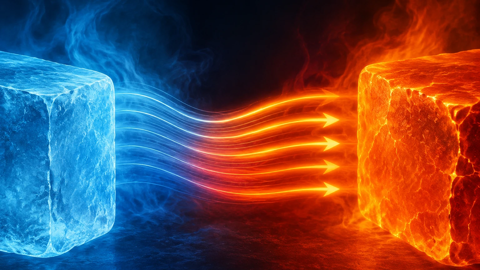
Thermal energy is the internal energy of an object due to the kinetic energy of its atoms and molecules. According to the Second Law of Thermodynamics, when two systems with different temperatures are placed in thermal contact, energy will transfer between them until thermal equilibrium is reached.
Directionality and Equilibrium
To answer precisely in which direction does thermal energy flow, one must look at the temperature gradient. Heat always moves from the hotter object to the cooler one. This process continues until both objects reach the same temperature. In industrial level measurement, this means that heat from a 200°C (392°F) chemical reactor will constantly migrate toward the ambient environment or the sensor housing unless specific barriers are in place.
Modes of Heat Transfer
There are three primary mechanisms through which this energy flow occurs:
1. Conduction: The transfer of energy through direct contact between solids or within a fluid. In a tank, heat conducts through the vessel walls and the mounting flanges of a level transmitter.
2. Convection: The transfer of heat by the physical movement of a fluid (liquid or gas). In a storage tank, rising warm vapors can transfer significant thermal energy to sensors located at the top of the vessel.
3. Radiation: The transfer of energy through electromagnetic waves. High-temperature processes, such as molten glass or metal, emit infrared radiation that can heat a level sensor even without direct physical contact or air movement.
Impact of Thermal Energy on Level Measurement Technologies
Every level measurement technology interacts with thermal energy differently. Understanding these interactions is critical for maintaining process safety and data integrity.
Ultrasonic Level Sensors
Ultrasonic sensors measure the time it takes for a sound wave to travel to the liquid surface and back. However, the speed of sound is highly dependent on the temperature of the medium through which it travels. In air, sound travels faster as temperature increases. If a sensor is calibrated for 20°C (68°F) but the actual vapor space is 60°C (140°F), the sensor will report an incorrect distance. Most professional-grade ultrasonic transmitters include integrated temperature compensation to account for this specific thermal flow.
Radar Level Meters
Radar level meters use electromagnetic waves, which are significantly less affected by temperature fluctuations than sound waves. However, the electronics within the radar head are sensitive to heat. Because thermal energy flows from the hot process toward the cooler electronics, high-temperature applications require specialized cooling fins or wave-guide extensions to dissipate heat before it reaches the sensitive circuitry. You can Review product options and application support to see how different radar designs handle extreme thermal gradients.
Hydrostatic Pressure Transmitters
Hydrostatic level measurement relies on the formula $P = \rho gh$ (Pressure = Density × Gravity × Height). Because thermal energy flow changes the temperature of the liquid, it also changes the liquid's density ($\rho$). If a tank is heated, the liquid expands and its density decreases. A pressure sensor at the bottom of the tank will see the same pressure even if the physical volume (level) has increased due to thermal expansion. Compensation for these density changes is required for mass-based level calculations.
Magnetic Level Gauges
Magnetic level gauges utilize a float inside a bypass chamber. As thermal energy flows into the chamber from the process, the liquid and the float both experience thermal expansion. In extreme cases, the change in liquid density may cause the float to sink or sit lower in the fluid, leading to inaccurate visual readings. Furthermore, extreme heat can affect the magnetic properties of the materials if the Curie point is approached, though this is rare in standard industrial applications.
Practical Selection Table for Thermal Environments
When selecting a level measurement solution, the thermal operating range is often the first constraint. The following table provides a comparison of common technologies and their typical thermal tolerances.
| Technology | Typical Temp Range (°C) | Thermal Sensitivity | Primary Heat Concern |
| :— | :— | :— | :— |
| Ultrasonic | -40 to 95 | High | Speed of sound variation |
| Radar (Non-Contact) | -196 to 450+ | Low | Electronic component overheating |
| Guided Wave Radar | -196 to 450 | Low | Probe thermal expansion |
| Hydrostatic | -40 to 120 | Moderate | Fluid density changes |
| Magnetic Gauge | -196 to 400 | Moderate | Float buoyancy & chamber expansion |
| Level Switches | -50 to 250 | Low | Seal and gasket degradation |
Installation Considerations for Managing Heat
Knowing in which direction does thermal energy flow allows engineers to design installation configurations that protect instruments.
1. Standoff Pipes and Nozzles
In high-temperature applications, mounting a sensor directly on the tank roof can expose it to maximum convective heat. Using a standoff pipe or an extended nozzle allows a buffer of cooler air to exist between the process and the sensor. For radar meters, this distance allows the thermal energy to dissipate through the pipe walls via conduction and convection to the ambient air.
2. Heat Tracing and Insulation
In some applications, the goal is to prevent thermal energy from flowing *out* of the process. For example, if a liquid is highly viscous and must be kept warm to flow, the level measurement chamber (such as in a magnetic level gauge or a bypass pipe) must be heat-traced and insulated. This ensures the fluid inside the measurement device remains at the same temperature and density as the fluid inside the main vessel.
3. Cooling Fins and Heat Sinks
For transmitters mounted in areas where ambient temperatures are high or process heat is intense, cooling fins are often integrated into the neck of the instrument. These fins increase the surface area available for convective heat transfer to the atmosphere, effectively "bleeding off" thermal energy before it reaches the internal electronics.
4. Remote Electronics
When the process temperature exceeds the limits of the sensor's electronics, a split-architecture design is used. The sensing element (e.g., a pressure diaphragm or a radar antenna) is mounted on the vessel, while the transmitter electronics are located several meters away in a cooler environment, connected by a cable or capillary tube.
Limitations and Technical Challenges
While we can predict the direction of thermal energy flow, managing it remains challenging in several scenarios:
* Thermal Stratification: In large storage tanks, the temperature may not be uniform. Heat may flow into the tank from the sun, creating a warm layer at the top while the bottom remains cool. This stratification can cause non-linear errors in ultrasonic and hydrostatic measurements.
* Rapid Thermal Cycling: Frequent and rapid changes in temperature (thermal shock) can cause mechanical fatigue in sensor diaphragms and seals. Materials expand and contract at different rates, which can eventually lead to seal failure or "drift" in the calibration.
* Ambient Temperature Extremes: In outdoor installations, the direction of thermal energy flow can reverse between day and night. A sensor might be heated by the process during the night but heated by the sun during the day, requiring robust housing and UV protection.
Frequently Asked Questions (FAQ)
Q: Does thermal energy flow differently in a vacuum?
In a vacuum, conduction and convection cannot occur because there is no medium (matter) to transfer the energy. However, thermal energy still flows via radiation. This is a critical consideration for level sensors used in vacuum distillation columns or space-simulated environments.
Q: How does humidity affect the flow of thermal energy in level measurement?
Humidity changes the heat capacity of the air in the vapor space. For ultrasonic sensors, high humidity can also affect the speed of sound and the rate of signal attenuation, often necessitating more frequent calibration or advanced signal processing.
Q: Can I use a standard level sensor for cryogenic applications?
No. In cryogenic applications, the thermal energy flow is from the ambient environment *into* the process. This causes extreme icing on the outside of the vessel and sensors. Specialized materials and vacuum-jacketed extensions are required to prevent the sensor from failing due to extreme cold and to minimize heat leak into the process.
Q: What is the most "thermally stable" level measurement technology?
Radar (both non-contact and guided wave) is generally considered the most thermally stable because electromagnetic waves are not significantly influenced by the temperature, pressure, or vapor composition of the headspace. However, the physical hardware must still be rated for the specific temperature of the application.
Conclusion
Understanding in which direction does thermal energy flow is the cornerstone of reliable industrial instrumentation. By acknowledging that heat will always seek the coolest path, engineers can proactively design systems that mitigate the risks of thermal expansion, density shifts, and electronic failure.
Selecting the right technology involves balancing the physical properties of the process fluid with the environmental conditions of the plant. Whether it is utilizing the high-temperature resilience of a radar meter or applying density compensation to a hydrostatic transmitter, managing thermal energy is essential for precision. For those seeking to optimize their process monitoring, it is advisable to consult with specialists and Review product options and application support to ensure that the chosen equipment is engineered to withstand the specific thermal dynamics of the intended application.
Download In Which Direction Does Thermal Energy Flow as a PDF