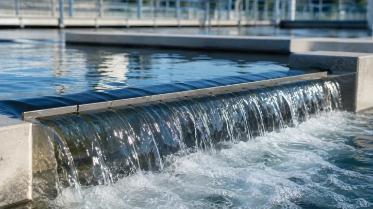
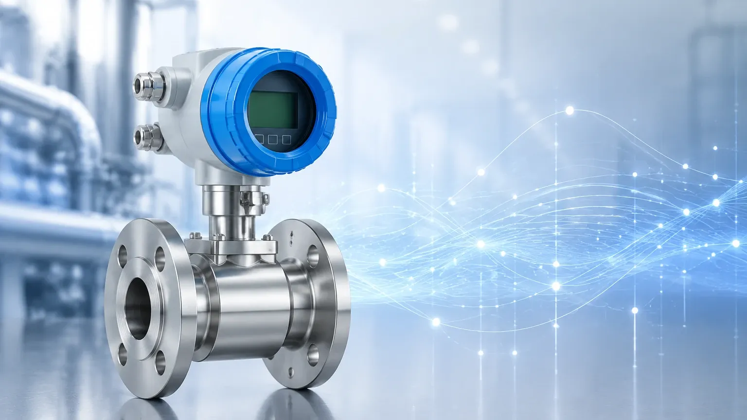
Flow Transmitter
Flow Transmitter
In the landscape of industrial process automation, a flow transmitter serves as a critical bridge between physical fluid dynamics and electronic control systems. While level measurement instruments—such as those found on the Main Page of industrial catalogs—monitor the volume of inventory within a vessel, a flow transmitter quantifies the rate at which fluids move through a system. This data is indispensable for billing, process optimization, and safety monitoring in industries ranging from water treatment and chemical processing to oil and gas production.
Understanding the specific measurement principles, selection criteria, and installation requirements is essential for engineers and plant managers to ensure long-term accuracy and system reliability.
Core Measurement Principles of Flow Transmitters
A flow transmitter does not measure flow directly; instead, it measures a secondary physical property (such as velocity, pressure drop, or thermal displacement) and converts that measurement into a standardized output signal, typically 4-20mA, HART, or Modbus. The choice of measurement principle depends heavily on the fluid's characteristics and the application requirements.
Differential Pressure (DP) Flow Measurement
Differential pressure is one of the most established methods for measuring flow. It relies on Bernoulli’s principle, which states that as the speed of a moving fluid increases, the pressure within the fluid decreases. By placing a primary element—such as an orifice plate, Venturi tube, or flow nozzle—inside the pipe, a deliberate pressure drop is created. The flow transmitter measures the pressure difference between the upstream and downstream sides of the restriction. The flow rate is proportional to the square root of this differential pressure.
Electromagnetic Flow Measurement
Often referred to as "magmeters," these transmitters operate based on Faraday’s Law of Electromagnetic Induction. When a conductive liquid flows through a magnetic field generated by the transmitter, it induces a voltage. This voltage is directly proportional to the velocity of the liquid. Because there are no moving parts and no internal obstructions, electromagnetic flow transmitters are ideal for slurries and corrosive chemicals, provided the fluid meets a minimum conductivity threshold (usually 5 μS/cm).
Ultrasonic Flow Measurement
Ultrasonic transmitters use sound waves to determine fluid velocity. There are two primary types:
1. Transit-Time: These use two transducers that send and receive signals. The time difference between the signal traveling with the flow and against the flow is used to calculate velocity. This is best for clean liquids.
2. Doppler: These reflect sound waves off particles or bubbles in the fluid. The frequency shift (Doppler effect) determines the velocity. This is preferred for aerated liquids or slurries.
Vortex Flow Measurement
Vortex transmitters utilize the von Kármán effect. When a fluid meets a "shedder bar" inside the transmitter, it creates alternating vortices (swirls). The frequency at which these vortices are shed is directly proportional to the fluid velocity. This technology is highly versatile, capable of measuring liquids, gases, and steam.
Selection Criteria for Industrial Applications
Choosing the correct flow transmitter requires a detailed analysis of the process environment. Selecting an incompatible technology can lead to measurement drift, frequent maintenance, or total sensor failure.
Fluid Characteristics
The most important factor is the state of the fluid. Is it a clean liquid, a gas, steam, or a slurry?
* Conductivity: If the fluid is non-conductive (like deionized water or hydrocarbons), electromagnetic meters cannot be used.
* Viscosity: High-viscosity fluids can cause significant pressure drops in DP meters and may affect the linearity of turbine meters.
* Corrosivity: The wetted parts of the transmitter must be chemically compatible with the process media. Tantalum, Hastelloy, and PTFE linings are common in chemical applications.
Process Conditions
Engineers must confirm the operating temperature and pressure. For instance, high-pressure steam applications often require robust vortex or DP transmitters designed for extreme thermal stress. Additionally, the required accuracy (e.g., ±0.5% vs. ±2.0% of rate) and the turndown ratio (the range over which the meter can measure accurately) will dictate the technology choice.
Pipe Size and Configuration
The physical dimensions of the installation site matter. While a small 25 mm (1 inch) pipe can accommodate almost any transmitter type, large diameter pipes (over 500 mm) may make full-bore electromagnetic or ultrasonic meters cost-prohibitive. In these cases, insertion-style transmitters or external clamp-on ultrasonic meters are often preferred.
Practical Selection Table
| Technology | Fluid Type | Accuracy | Typical Turndown | Advantages | Limitations |
| :— | :— | :— | :— | :— | :— |
| Differential Pressure | Liquid, Gas, Steam | ±0.5% to ±2% | 4:1 | Low cost, well-understood | High pressure drop, requires straight runs |
| Electromagnetic | Conductive Liquids | ±0.2% to ±0.5% | 20:1 | No moving parts, low maintenance | Requires conductivity, liquid only |
| Ultrasonic (Transit-Time) | Clean Liquids | ±0.5% to ±1% | 50:1 | Non-invasive (clamp-on), no pressure drop | Sensitive to bubbles/solids |
| Vortex | Liquid, Gas, Steam | ±0.5% to ±1% | 10:1 | Versatile, handles high temp | Sensitive to vibration, minimum flow required |
| Turbine | Clean Liquids/Gases | ±0.25% | 10:1 | High precision | Moving parts wear out, sensitive to viscosity |
Installation Considerations and Best Practices
Even the most advanced flow transmitter will fail to provide accurate data if installed incorrectly. Proper installation is the most significant factor in long-term performance.
Straight Pipe Requirements
Most flow measurement technologies require a fully developed flow profile to ensure accuracy. This means the fluid should be moving in a predictable, non-turbulent manner. To achieve this, transmitters usually require a specific length of straight pipe upstream (typically 10 to 20 pipe diameters) and downstream (typically 5 pipe diameters) from any elbows, valves, or pumps. If space is limited, flow conditioners or vaned inserts may be necessary to reduce turbulence.
Orientation and Mounting
For liquid applications, the transmitter should ideally be installed in a vertical pipe with the flow moving upward. This ensures the pipe remains full and prevents air pockets from collecting at the sensor head. If horizontal installation is necessary, the transmitter should be placed at a low point in the piping system. For gas applications, the transmitter should be placed at a high point to prevent condensate from accumulating in the sensor.
Grounding and Signal Integrity
Electromagnetic flow transmitters are particularly sensitive to electrical noise. Proper grounding of the fluid and the transmitter body to the earth is mandatory to prevent stray currents from interfering with the low-voltage signals generated by the sensor. Furthermore, signal cables should be shielded and kept away from high-voltage power lines to prevent electromagnetic interference (EMI).
Limitations and Common Risks
While modern flow transmitters are highly reliable, they are not "set and forget" devices. Users should be aware of the following risks:
1. Scaling and Coating: In wastewater or chemical applications, material can build up on the internal walls of the meter or the electrodes. This changes the internal diameter of the pipe or insulates the sensors, leading to significant measurement errors.
2. Cavitation and Flashing: If the pressure drops too low within the transmitter (common in DP or Vortex meters), the liquid may vaporize, forming bubbles. This phenomenon, known as cavitation, can erode the internal components and cause erratic readings.
3. Two-Phase Flow: Most flow transmitters are designed for single-phase flow (100% liquid or 100% gas). The presence of air bubbles in a liquid line or liquid droplets in a gas line will cause most meters to report highly inaccurate data.
The Relationship Between Level and Flow
In many industrial setups, level and flow measurement are inextricably linked. For example, in open-channel flow (such as a wastewater flume), a level meter is used to measure the height of the liquid. This height is then converted into a flow rate using a standard formula related to the geometry of the flume.
Furthermore, many plants that utilize flow transmitters for process control also rely on hydrostatic level transmitters or radar level meters for inventory management. Integrating these sensors into a unified control loop allows for mass balance calculations, which are essential for detecting leaks or process inefficiencies. For those looking to explore how these systems integrate, reviewing professional instrument options on the Main Page can provide insights into the hardware required for a complete automation solution.
Frequently Asked Questions (FAQ)
Q: How often should a flow transmitter be calibrated?
A: Calibration frequency depends on the application's criticality and the technology used. Typically, an annual calibration check is recommended for billing or safety-critical applications. Some modern digital transmitters offer self-diagnostic features that can extend the time between physical calibrations.
Q: Can a flow transmitter measure mass flow?
A: Most standard flow transmitters measure volumetric flow (e.g., liters per minute). To measure mass flow (e.g., kilograms per hour), you must either use a Coriolis meter or calculate it using a multivariable transmitter that also measures the fluid's temperature and pressure to account for density changes.
Q: What is the difference between a flow sensor and a flow transmitter?
A: The flow sensor is the primary element that physically interacts with the fluid (like a turbine wheel or an orifice plate). The flow transmitter is the electronic component that takes the raw signal from the sensor and converts it into a usable output for a PLC or DCS.
Q: Why is my electromagnetic flow meter reading zero when there is flow?
A: This is often caused by the fluid not being sufficiently conductive, or the pipe not being completely full. It can also occur if the grounding is improper, causing the signal to be lost in electrical noise.
By following these guidelines and understanding the underlying physics of flow measurement, engineering teams can select the most cost-effective and reliable flow transmitter for their specific industrial needs.