Differential Transmitter
Differential Transmitter
In the landscape of industrial process control, the differential transmitter stands as one of the most versatile and widely implemented instruments for level measurement. While its primary function is to measure the difference between two pressure points, its application in determining the level of liquids within tanks—both atmospheric and pressurized—is a cornerstone of modern automation. For engineers and procurement specialists, understanding the nuances of how a differential transmitter operates, its installation requirements, and its limitations is essential for ensuring process safety and accuracy.
This guide provides a comprehensive technical overview of differential pressure (DP) technology, specifically tailored for level measurement applications in water treatment, chemical processing, and oil and gas industries.
Fundamental Principles of Differential Pressure Level Measurement
The operation of a differential transmitter in a level measurement context is based on the principle of hydrostatic pressure. According to Pascal’s Law, the pressure exerted by a liquid column at rest is proportional to the height of the liquid and its specific gravity. The mathematical relationship is expressed as:
P = ρ · g · h
Where:
* P is the hydrostatic pressure.
* ρ (rho) is the density of the liquid.
* g is the acceleration due to gravity (approximately 9.81 m/s²).
* h is the height of the liquid column.
A differential transmitter measures the difference between a high-pressure (HP) side and a low-pressure (LP) side. In level applications, the HP side is typically connected to the bottom of the vessel, where the pressure is highest due to the weight of the liquid. The LP side's connection depends on whether the tank is open to the atmosphere or pressurized.
Open Tank (Atmospheric) Applications
In an open tank, the surface of the liquid is subject to atmospheric pressure. To measure the level, the HP side of the differential transmitter is connected to the bottom of the tank, while the LP side is vented to the atmosphere. Since atmospheric pressure acts on both the liquid surface and the LP side of the transmitter, the two cancel each other out, leaving only the pressure exerted by the liquid column to be measured.
Closed Tank (Pressurized) Applications
In closed vessels, such as boilers or chemical reactors, the space above the liquid (the headspace) is often pressurized with gas or vapor. This headspace pressure adds to the hydrostatic pressure at the bottom of the tank. To isolate the liquid level, the LP side of the differential transmitter is connected to the top of the vessel. This ensures that the headspace pressure is applied to both sides of the transmitter's sensing element, effectively "subtracting" it and providing a measurement based solely on the liquid height.
Key Components and Configuration
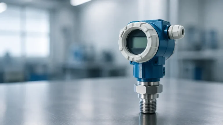
A standard industrial differential transmitter consists of several critical components that determine its performance and suitability for specific environments.
1. Sensing Element: Usually a flexible diaphragm (made of stainless steel, Hastelloy, or Tantalum) that moves in response to pressure changes. This movement is converted into an electrical signal, typically via capacitive or piezoresistive sensors.
2. Transmitter Electronics: The circuitry that processes the raw sensor signal into a standardized output, such as 4-20 mA with HART, Foundation Fieldbus, or Profibus protocols.
3. Process Flanges and Manifolds: These provide the physical connection to the process piping. A three-valve or five-valve manifold is frequently used to allow for the isolation and calibration of the transmitter without shutting down the process.
4. Impulse Lines or Remote Seals: These are the conduits that transmit the process pressure to the sensing element. Impulse lines are small-bore pipes, while remote seals (capillary systems) use a flexible diaphragm and a fill fluid (like silicone oil) to transmit pressure, which is ideal for corrosive or high-temperature media.
When reviewing technical specifications on a manufacturer's Main Page, it is vital to match these components to the chemical compatibility and temperature requirements of the specific application.
Selection Criteria and Technical Specifications
Choosing the correct differential transmitter requires a detailed analysis of the process conditions. Engineers should evaluate the following criteria before procurement:
Pressure Range and Turndown Ratio
The transmitter must be capable of measuring the maximum hydrostatic head expected in the tank. The "turndown ratio" refers to the range over which the transmitter can be calibrated while maintaining its accuracy. For example, a transmitter with a 100:1 turndown ratio offers significant flexibility for varying tank sizes.
Material Compatibility
The wetted parts—those in direct contact with the process fluid—must resist corrosion. Common materials include:
* 316L Stainless Steel: Standard for water and non-corrosive chemicals.
* Hastelloy C-276: Used for aggressive acids and chlorides.
* Tantalum: Reserved for highly corrosive applications like sulfuric acid.
Accuracy and Stability
Industrial-grade transmitters typically offer accuracy ranging from ±0.04% to ±0.1% of the calibrated span. Long-term stability is also a factor, representing how much the measurement drifts over time (e.g., ±0.1% per year).
Environmental Ratings
For outdoor or hazardous installations, the transmitter housing must meet specific ingress protection (IP66/67) and explosion-proof (ATEX/IECEx) certifications.
Installation Guidelines and Best Practices
Proper installation is the most critical factor in ensuring the reliability of a differential transmitter. Errors in mounting can lead to significant measurement offsets.
Zero Elevation and Suppression
In many installations, the transmitter is not mounted exactly at the 0% level mark of the tank.
* Zero Suppression: Used when the transmitter is mounted below the tank bottom. The weight of the liquid in the impulse line creates a positive pressure even when the tank is empty. The transmitter must be "suppressed" to read zero at this point.
* Zero Elevation: Used in closed tanks with "wet legs" (where the LP impulse line is filled with liquid to prevent vapor condensation). The weight of the wet leg creates a constant pressure on the LP side, requiring a zero elevation adjustment.
Impulse Line Routing
Impulse lines should be sloped to allow gas bubbles to escape back into the tank (for liquid service) or to allow condensate to drain (for gas service). A typical slope of 1:12 (8%) is recommended. For high-viscosity or slurry applications, remote seals are preferred over impulse lines to prevent clogging.
Manifold Usage
Always install a manifold. This allows the operator to "zero" the transmitter under static pressure by closing the process valves and opening the equalizing valve, ensuring the transmitter sees the same pressure on both sides.

Practical Selection Table: Technology Comparison
While the differential transmitter is a workhorse, it is not always the best fit. The following table compares DP technology with other common level measurement methods found in the Welk product portfolio.
| Technology | Best For | Advantages | Limitations |
| :— | :— | :— | :— |
| Differential Pressure | Pressurized tanks, high temp | Proven, versatile, cost-effective | Sensitive to density changes |
| Radar (Non-contact) | Corrosive liquids, bulk solids | High accuracy, no moving parts | Higher initial cost |
| Ultrasonic | Open channels, water tanks | Low cost, easy installation | Affected by foam and steam |
| Magnetic Level Gauge | Visual indication, high pressure | Redundant measurement, clear visual | Mechanical parts can wear |
| Hydrostatic (Submersible) | Deep wells, open reservoirs | Simple, robust | Not suitable for pressurized tanks |
Limitations and Troubleshooting Common Issues
Despite its reliability, the differential transmitter has inherent limitations that must be managed through engineering design.
Density Variations
Since a DP transmitter measures mass (weight), any change in the liquid's density will result in a level error. If the temperature of the liquid fluctuates significantly, its density changes, and the transmitter will report an incorrect level even if the physical height remains the same. In such cases, temperature compensation or a different technology (like radar) may be required.
Gas Pockets and Condensation
In "dry leg" installations (where the LP line is filled with gas), condensation can accumulate in the line, creating an unintended liquid head that offsets the measurement. Regular "blow-down" of impulse lines or the use of a wet leg/remote seal is necessary to mitigate this risk.
Diaphragm Fatigue
In applications with frequent pressure spikes or extreme temperatures, the sensing diaphragm can suffer from fatigue or permanent deformation. Selecting a transmitter with over-pressure protection and appropriate fill fluids for the operating temperature range is essential.
Frequently Asked Questions (FAQ)
Q: Can a differential transmitter measure the level of a slurry?
A: Yes, but standard impulse lines will likely clog. It is highly recommended to use a differential transmitter equipped with remote diaphragm seals and large-diameter process connections to prevent media buildup.
Q: How often should a differential transmitter be calibrated?
A: While modern digital transmitters are very stable, a standard practice is to verify the calibration every 1 to 2 years. However, in critical safety loops or highly corrosive environments, more frequent checks may be necessary.
Q: What is the difference between a pressure transmitter and a differential transmitter?
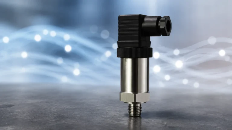
A: A standard pressure transmitter has one process connection and measures pressure relative to the atmosphere (gauge) or a vacuum (absolute). A differential transmitter has two connections and measures the specific difference between them, which is necessary for closed-tank level and flow applications.
Q: How do I handle a pressurized tank with a boiling liquid?
A: Boiling liquids create vapors that can condense in the impulse lines. A "wet leg" (pre-filling the LP line with a compatible liquid) or a remote seal system is the standard engineering solution for this scenario.
Conclusion and Next Steps
The differential transmitter remains a fundamental tool for industrial level measurement due to its adaptability and the depth of engineering knowledge surrounding its use. By carefully considering the liquid density, tank pressure, and installation geometry, process engineers can achieve highly accurate and repeatable results.
For those looking to integrate these instruments into their systems, it is advisable to consult technical datasheets and application notes to confirm material compatibility and range requirements. You can Review product options and application support to find the specific configuration that meets your industrial automation needs. Whether dealing with standard water treatment or complex chemical reactors, selecting the right differential transmitter is a critical step toward operational efficiency and safety.