Indirect Potable Water Reuse
Indirect Potable Water Reuse
Indirect potable water reuse (IPWR) represents a critical pillar in modern sustainable water management. As global water scarcity intensifies due to climate variability and industrial expansion, the ability to transform treated municipal wastewater into a reliable drinking water source is no longer an alternative—it is a necessity. Unlike direct potable reuse, IPWR incorporates an environmental buffer, such as an aquifer or a surface water reservoir, before the water is treated again for human consumption.
For engineers and utility managers, the success of an indirect potable water reuse project depends on the precision of the treatment process and the reliability of the monitoring systems. Level measurement is fundamental to this infrastructure, ensuring that tanks do not overflow, pumps do not run dry, and the environmental buffers are maintained at optimal stages. This article explores the technical requirements of IPWR and the instrumentation strategies necessary to support these complex systems.
The Process of Indirect Potable Water Reuse
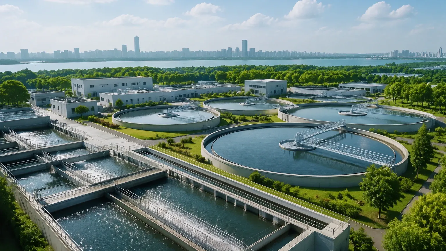
The IPWR cycle generally consists of three primary phases: Advanced Water Purification, Environmental Buffering, and Final Potable Treatment. Each phase requires specific hydraulic controls and level monitoring to ensure safety and efficiency.
1. Advanced Water Purification Facility (AWPF)
In this stage, secondary or tertiary effluent from a wastewater treatment plant undergoes rigorous purification. This typically includes microfiltration (MF) or ultrafiltration (UF), reverse osmosis (RO), and an advanced oxidation process (AOP) such as UV/H2O2. Level sensors are required in feed tanks, permeate storage, and chemical dosing skids.
2. Environmental Buffer
The purified water is discharged into a "natural" barrier. This can be an underground aquifer (via injection wells or infiltration basins) or a surface reservoir. This buffer provides "environmental attenuation" and allows for a loss of identity of the recycled water, which is often a regulatory or public perception requirement. Monitoring the level of these buffers is essential for resource management and flood prevention.
3. Potable Water Treatment Plant (WTP)
Water is eventually withdrawn from the buffer and treated at a conventional water treatment plant. Here, it is blended with other raw water sources, filtered, and disinfected. Precise level control at the intake ensures a consistent blend ratio, which is vital for maintaining chemical dosing accuracy.
Measurement Principles for Level Instrumentation
Selecting the right technology for indirect potable water reuse applications requires an understanding of the physics behind the measurement. Below are the primary principles used in industrial level sensing.
Radar Level Measurement (FMCW)
Frequency Modulated Continuous Wave (FMCW) radar is the gold standard for high-accuracy applications. The sensor emits a continuous signal with a varying frequency. The reflection from the liquid surface is received, and the frequency difference between the emitted and received signal is proportional to the distance.
In IPWR, 80GHz radar is preferred because its narrow beam angle allows for installation in narrow tanks or near internal obstructions like agitators without interference. Because radar is non-contact, it is unaffected by changes in pressure, vacuum, or the presence of vapors, making it ideal for chemical storage and RO permeate tanks.
Ultrasonic Level Measurement
Ultrasonic sensors work on the Time-of-Flight (ToF) principle. The transducer emits an ultrasonic pulse that reflects off the liquid surface. The sensor calculates the distance based on the time it takes for the echo to return. While cost-effective, ultrasonic waves are affected by air temperature, humidity, and heavy foam. In water reuse, these are commonly used for open-channel flow measurement in flumes or for monitoring large, open equalization basins where high precision is less critical than in chemical dosing.
Hydrostatic Level Measurement
Hydrostatic transmitters measure the pressure exerted by a liquid column. The pressure ($P$) is equal to the height of the liquid ($h$) multiplied by the density ($
ho$) and gravity ($g$). In the context of indirect potable water reuse, submersible hydrostatic sensors are indispensable for monitoring groundwater levels in injection and recovery wells. They are robust and can be lowered into narrow piezometers to track the recharge of the aquifer.
Magnetic Level Gauges and Switches
Magnetic level gauges provide a high-visibility local indication by using a float containing a magnet that flips colored flaps in a chamber. These are often paired with reed switches or transmitters. In IPWR facilities, these are frequently used on tanks containing aggressive disinfection chemicals, providing a fail-safe mechanical backup to electronic sensors.
Technology Selection Table for IPWR Applications
| Application Stage | Recommended Technology | Primary Reason |
| :— | :— | :— |
| RO Permeate Storage | Radar (80GHz) | Non-contact, high precision, unaffected by humidity. |
| Chemical Dosing (Acids/Bases) | Radar or Magnetic Gauge | Corrosion resistance and material compatibility. |
| Groundwater Recharge Wells | Hydrostatic (Submersible) | Ability to measure at great depths in narrow spaces. |
| Open Buffering Reservoirs | Ultrasonic or Radar | Long-range measurement for large surface areas. |
| Filter Backwash Tanks | Ultrasonic | Cost-effective for water with suspended solids. |
| Sludge Thickening | Radar | Handles turbulence and surface crusting better than ultrasonic. |
Installation Considerations for Engineering Success
Proper installation is as important as technology selection. When designing systems for indirect potable water reuse, engineers should consider the following:
1. Blocking Distance (Dead Zone): Every non-contact sensor has a minimum distance it cannot measure near the transducer. Ensure the maximum expected liquid level does not enter this zone to avoid signal loss.
2. Stilling Wells: In tanks with high turbulence or foam (common in aeration or mixing stages), a stilling well or bypass pipe can provide a calm surface for the sensor to track, significantly improving reliability.
3. Atmospheric Compensation: For hydrostatic sensors used in deep wells, ensure the cable includes a vent tube to compensate for changes in atmospheric pressure, which can otherwise cause errors in level readings.
4. Chemical Compatibility: In the advanced oxidation and disinfection stages of IPWR, sensors are exposed to ozone, chlorine, or hydrogen peroxide. Ensure wetted parts (e.g., PVDF, PTFE, or high-grade Stainless Steel) are rated for these environments.
Limitations and Risks
While modern instrumentation is highly reliable, certain conditions in an indirect potable water reuse project can challenge performance:
* Foam Accumulation: Heavy foam can absorb ultrasonic signals and scatter radar signals. In such cases, high-frequency radar or contact-based hydrostatic sensors are more reliable.
* Vapor and Condensation: In warm water applications, condensation can form on the sensor face. Modern radar sensors often feature drip-off lens designs to mitigate this, whereas ultrasonic sensors may fail if the transducer face is obscured by droplets.
* Signal Interference: Internal tank structures like ladders, pipes, or agitators can create "false echoes." Advanced software in modern transmitters allows for "False Signal Suppression," where the sensor learns and ignores these static reflections.
Frequently Asked Questions (FAQs)
Q: Why is radar preferred over ultrasonic for RO permeate tanks?
A: RO permeate is high-purity water. Ultrasonic sensors are sensitive to the air temperature and humidity inside the tank, which can fluctuate. Radar is unaffected by these atmospheric changes and provides the millimeter-level precision required for tight process control.
Q: How do you monitor level in deep groundwater injection wells?
A: Submersible hydrostatic transmitters are the standard. They are designed with IP68 ingress protection and can be lowered hundreds of meters into the ground. They track the "head" of water above the sensor to determine the aquifer level.
Q: Can level sensors help in meeting regulatory requirements for IPWR?
A: Yes. Regulatory bodies often require proof of "Log Reduction Credits" for pathogens. While level sensors don't measure pathogens, they ensure that the contact time in disinfection tanks is maintained by keeping the water at the required level, thus supporting the overall validation of the treatment process.
Q: What maintenance is required for these sensors?
A: Non-contact sensors like radar require very little maintenance. Hydrostatic sensors should be checked periodically for sediment buildup around the diaphragm, especially in raw water or environmental buffer applications.
Conclusion
Implementing indirect potable water reuse is a complex engineering feat that demands the highest standards of accuracy and reliability. From the advanced membranes of the purification facility to the depths of the environmental buffer, level measurement ensures that every drop of water is accounted for and processed correctly. By understanding the principles of radar, ultrasonic, and hydrostatic measurement, engineers can build resilient systems that safeguard our water future.
To explore specific instrumentation for your water reuse project, you can Review product options and application support on our Main Page. Selecting the right tool for the application is the first step toward operational excellence in the water industry.