Industrial Flow Meters
Industrial Flow Meters
In the landscape of industrial process control, the ability to accurately quantify the movement of liquids, gases, and steam is fundamental to operational efficiency, safety, and fiscal accountability. Industrial flow meters serve as the primary sensory organs for these systems, providing real-time data that informs automated valves, pumps, and safety shutdowns. While level measurement instruments—such as those found on our Main Page—monitor the inventory within a vessel, flow meters measure the rate at which that inventory enters or exits the process. Together, these technologies provide a comprehensive mass balance that is critical for industries ranging from wastewater treatment to chemical processing.
Selecting the appropriate industrial flow meters requires a deep understanding of fluid dynamics, pipe geometry, and the physical properties of the media being measured. This guide examines the core measurement principles, selection criteria, and installation best practices necessary for successful deployment in demanding industrial environments.
Core Principles of Flow Measurement
Before selecting a meter, it is essential to understand the physics governing different measurement technologies. Industrial flow meters are generally categorized by the physical principle they employ to derive flow rate.
Electromagnetic Measurement (Magmeters)
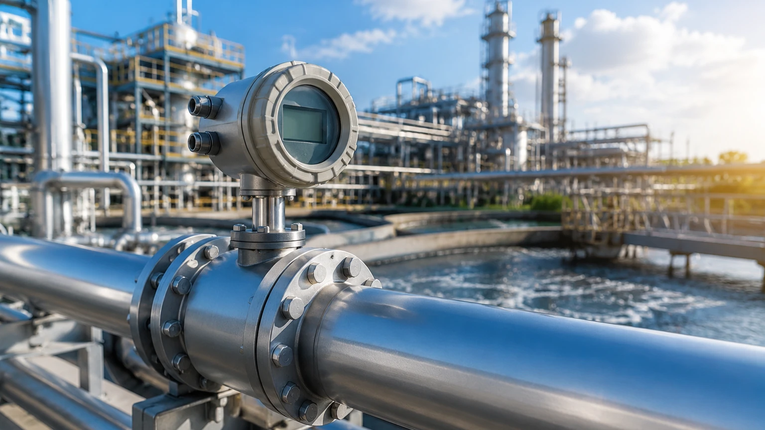
Electromagnetic flow meters operate based on Faraday’s Law of Induction. This principle states that a conductor moving through a magnetic field produces an electrical signal directly proportional to the velocity of the conductor. In this application, the conductive liquid (such as water or acids) acts as the conductor. As the fluid flows through a magnetic field generated by coils in the meter body, electrodes detect the voltage.
Because there are no moving parts and no obstructions in the flow path, magmeters offer extremely low pressure drop and are highly resistant to wear. However, they require the fluid to have a minimum level of electrical conductivity, typically >5 μS/cm, making them unsuitable for hydrocarbons or deionized water.
Ultrasonic Measurement
Ultrasonic meters use sound waves to determine fluid velocity. There are two primary types:
1. Transit-Time: These meters send ultrasonic pulses diagonally across the pipe. The pulse traveling with the flow moves faster than the pulse traveling against it. The difference in time is proportional to the flow velocity. These are ideal for clean liquids.
2. Doppler: These meters reflect sound waves off bubbles or particles in the flow. The frequency shift (Doppler effect) of the reflected wave indicates the velocity. These are preferred for aerated liquids or slurries.
Vortex Shedding
Vortex meters utilize the Von Kármán effect. When a fluid meets a "shedder bar" (a non-streamlined object) placed in the flow stream, it creates alternating vortices on either side. The frequency at which these vortices are shed is directly proportional to the fluid velocity. Vortex meters are highly versatile, capable of measuring liquids, gases, and saturated steam, and are known for their long-term stability since they have no moving parts to wear out.
Differential Pressure (DP)
DP flow meters are among the oldest and most common technologies. They work by placing a constriction in the pipe (such as an orifice plate or Venturi tube) to create a pressure drop. According to Bernoulli’s equation, the square root of the pressure drop is proportional to the flow rate. While reliable and well-understood, DP meters introduce a permanent pressure loss and require impulse piping that can be prone to leaks or clogging.
Coriolis (Mass Flow)
Unlike the previous technologies which measure volumetric flow, Coriolis meters measure mass flow directly. As fluid moves through a vibrating tube, it creates a Coriolis force that causes the tube to twist. The amount of twist is directly proportional to the mass flow rate. These meters are exceptionally accurate and can also measure fluid density and temperature simultaneously, though they represent a higher capital investment.
Industrial Flow Meters Selection Criteria
Choosing the right meter involves balancing performance requirements against the physical constraints of the application. Engineers should evaluate the following factors:
Fluid Properties
* State: Is the media a liquid, gas, or steam?
* Conductivity: Required for electromagnetic meters.
* Viscosity: High-viscosity fluids may require positive displacement or Coriolis meters.
* Corrosivity: Determines the materials of construction for liners and electrodes (e.g., PTFE, Hastelloy, or Stainless Steel).
* Cleanliness: Does the fluid contain solids or bubbles? This affects the choice between transit-time and Doppler ultrasonic meters.
Process Conditions
* Flow Range (Turndown Ratio): The ratio of the maximum flow to the minimum flow the meter can accurately measure. Vortex and DP meters typically have lower turndown ratios compared to ultrasonic or electromagnetic options.
* Pressure and Temperature: Ensure the meter body and sensors are rated for the maximum process limits. Steam applications, for instance, require high-temperature-rated vortex or DP sensors.
* Accuracy Requirements: Custody transfer applications require high-precision Coriolis meters (0.1% accuracy), while simple process monitoring might only require ±1.0% to ±2.0% accuracy.
Physical Constraints
* Pipe Size: Meters for large pipes (above 300 mm) can become prohibitively expensive in full-bore configurations, making insertion-style meters or clamp-on ultrasonic meters more cost-effective.
* Straight Run Availability: Most flow meters require a specific length of straight pipe upstream and downstream to ensure a stable, non-turbulent flow profile.
Technical Comparison Table
| Technology | Typical Accuracy | Fluid Types | Advantages | Limitations |
| :— | :— | :— | :— | :— |
| Electromagnetic | ±0.5% | Conductive Liquids | No pressure drop; no moving parts. | Requires conductivity; not for gases. |
| Ultrasonic | ±0.5% to ±2% | Liquids/Gases | Non-intrusive (clamp-on); no pressure drop. | Sensitive to flow profile/turbulence. |
| Vortex | ±1.0% | Liquid, Gas, Steam | Wide temp range; no moving parts. | Minimum Reynolds number required. |
| Coriolis | ±0.1% | Liquids, Slurries | Direct mass flow; extremely accurate. | High initial cost; size limitations. |
| Differential Pressure | ±1.0% to ±3% | Liquid, Gas, Steam | Low cost; industry standard. | High pressure drop; maintenance-heavy. |
Installation and Engineering Considerations
Proper installation is as critical as meter selection. Even the most advanced industrial flow meters will provide inaccurate data if installed incorrectly.
Flow Profile and Straight Runs
Flow meters generally require a "fully developed flow profile." Obstructions like elbows, valves, and reducers create turbulence and swirl. A common rule of thumb is to provide 10 pipe diameters (10D) of straight pipe upstream and 5 pipe diameters (5D) downstream of the meter. If these distances cannot be met, flow conditioners or specific technologies like dual-sensor ultrasonic meters may be required.
Pipe Orientation and Filling
For liquid applications, the pipe must be completely full for the meter to read accurately.
* Vertical Upward Flow: This is the ideal orientation for liquid flow as it ensures a full pipe and prevents air entrapment.
* Horizontal Flow: Acceptable, but the meter should not be placed at the highest point of a piping system where air might collect, nor at the lowest point where sediment might settle.
* Vertical Downward Flow: Generally avoided for liquids because the pipe may not remain full, leading to significant measurement errors.
Grounding and Interference
Electromagnetic flow meters are particularly sensitive to electrical noise. Proper grounding of the meter body to the process fluid is essential, especially in plastic-lined or non-conductive piping. For ultrasonic meters, proximity to high-frequency variable frequency drives (VFDs) can cause signal interference and should be shielded.
Integration with Level Measurement Systems
In many industrial applications, flow and level measurement are used in tandem to provide a complete picture of process health. For example, in a chemical dosing tank, a level transmitter (details of which can be found on our Main Page) monitors the total volume available, while a flow meter ensures the precise amount of chemical is being injected into the process stream.
Discrepancies between the change in tank level and the integrated flow rate can indicate critical issues such as:
* Leaks: If the level drops faster than the flow meter indicates.
* Pump Inefficiency: If the pump is running but the flow meter shows lower-than-expected throughput.
* Meter Calibration Drift: If the two sensors consistently disagree over time.
By integrating these two data points into a centralized PLC (Programmable Logic Controller) or SCADA system, plant operators can implement automated mass-balance checks that improve safety and reduce waste.
Common Risks and Limitations
Despite advancements in technology, industrial flow meters face several operational risks:
1. Cavitation: In liquid flows, if the local pressure drops below the vapor pressure, bubbles form and collapse. This can physically damage the meter (especially turbine or DP types) and cause erratic readings.
2. Scaling and Coating: In wastewater or chemical processes, material can build up on the internal walls of the meter or on electrodes. This changes the internal diameter or insulates the sensors, leading to drift. Choosing a meter with a smooth liner (like PFA) or non-contact ultrasonic sensors can mitigate this.
3. Entrained Air: Even small amounts of air in a liquid line can cause ultrasonic signals to scatter or cause magmeters to read incorrectly. Air eliminators should be installed upstream if the process is prone to aeration.
4. Vibration: High levels of mechanical vibration from nearby pumps can interfere with the sensors in vortex or Coriolis meters. Proper pipe support and dampening are necessary.
Frequently Asked Questions (FAQs)
Q: Can I use one flow meter for both water and oil?
A: It depends on the technology. A vortex or ultrasonic meter can measure both, provided the viscosity of the oil is within the meter's limits. However, an electromagnetic meter will work for water but fail for oil, as oil is non-conductive.
Q: How often do industrial flow meters need calibration?
A: Calibration frequency depends on the criticality of the process and the technology used. Coriolis meters are very stable and may only need checking every few years. DP meters with orifice plates may need more frequent inspection for edge wear. Most regulated industries (e.g., pharma or food) require annual calibration.
Q: What is the difference between "Accuracy" and "Repeatability"?
A: Accuracy is how close the meter's reading is to the true value. Repeatability is the meter's ability to provide the same reading under the same conditions. In some control loops, high repeatability is more important than absolute accuracy.
Q: Can I install a flow meter immediately after a pump?
A: It is not recommended. Pumps create significant turbulence and pressure pulsations. It is best to place the meter on the discharge side after a sufficient straight run of pipe to allow the flow to stabilize.
Conclusion and Next Steps
Selecting the right industrial flow meter is a process of matching the physics of the measurement to the realities of the fluid and the installation environment. Before finalizing a specification, project teams should confirm the following:
* Media Compatibility: Ensure all wetted parts (liners, electrodes, sensors) are chemically compatible with the fluid.
* Flow Profile: Confirm that the installation site provides enough straight pipe run or plan for flow conditioners.
* Data Integration: Determine if the meter needs to output a 4-20mA signal, HART, Modbus, or Profibus to communicate with existing control systems.
* Maintenance Access: Ensure the meter is installed in a location where it can be reached for periodic calibration or cleaning.
For comprehensive process control, remember that flow measurement is only one part of the equation. Monitoring the vessels and tanks associated with these flows is equally vital. We encourage you to review our Main Page for a detailed look at level measurement solutions that complement your flow control strategy. By selecting high-quality instruments and following rigorous installation standards, industrial operators can ensure long-term accuracy and reliability in their most critical processes.