Installation of Ph Meter
Installation of Ph Meter
In industrial process control, the measurement of pH is a fundamental requirement for ensuring product quality, protecting equipment from corrosion, and meeting environmental discharge regulations. While the sensors themselves are sophisticated electrochemical devices, their performance is heavily dependent on correct physical placement and electrical integration. This guide provides a technical overview of the principles, selection criteria, and the detailed installation of ph meter systems in industrial environments.
Principles of pH Measurement
pH measurement is based on the potentiometric principle, typically utilizing a glass electrode and a reference electrode. The potential difference between these two electrodes is proportional to the hydrogen ion activity in the solution, which correlates to the pH value.
The Nernst Equation
The relationship between the measured potential and the pH value is defined by the Nernst Equation:
$$E = E_0 – \frac{2.303 RT}{nF} \log a_{H^+}$$
Where:
* E: Measured potential.
* E0: Standard potential of the electrode.
* R: Universal gas constant.
* T: Absolute temperature in Kelvin.
* n: Charge of the ion (for H+, n=1).
* F: Faraday constant.
* aH+: Activity of hydrogen ions.
In practical terms, at 25°C (298.15 K), a change of one pH unit corresponds to a theoretical change of 59.16 mV. Because this relationship is temperature-dependent, industrial pH systems must incorporate Automatic Temperature Compensation (ATC) to adjust the slope of the measurement based on the process temperature.
Electrode Components
1. Glass Electrode: Features a specialized pH-sensitive glass membrane that develops a charge proportional to the hydrogen ion concentration.
2. Reference Electrode: Provides a stable, known potential against which the glass electrode's potential is measured. It typically uses a silver/silver chloride (Ag/AgCl) system immersed in a potassium chloride (KCl) electrolyte.
3. Junction: A porous membrane (ceramic, PTFE, or wood) that allows electrical contact between the reference electrolyte and the process liquid while minimizing the mixing of the two.
Sensor Selection Criteria
Before proceeding with the installation of ph meter hardware, engineers must select a sensor configuration compatible with the specific process conditions. The following table outlines selection parameters for common industrial applications.
| Application Type | Recommended Sensor | Junction Material | Housing Material |
| :— | :— | :— | :— |
| Wastewater Treatment | General purpose glass | Ceramic or Porous PTFE | Polypropylene (PP) |
| Chemical Processing | High-temperature glass | Double junction PTFE | PVDF or Stainless Steel |
| Pure Water / Power | Low-impedance glass | Flowing liquid junction | Stainless Steel |
| Food & Beverage | ISFET (Solid-state) | Open aperture | Food-grade PEEK |
| Abrasive Slurries | Flat-surface glass | Double junction | Reinforced Polymer |
| Oil/Water Separation | Coated-resistant glass | Large surface ceramic | Stainless Steel |
Selecting the correct sensor ensures that the installation remains viable over a long service life. For more specialized instrumentation needs, including level measurement solutions that often complement pH monitoring in tank systems, users can refer to the Main Page of the product catalog.
Methods for the Installation of Ph Meter
The physical installation of a pH sensor is categorized by how the sensor interacts with the process stream. Each method has distinct advantages and requirements.
1. In-line Installation (Pipe Mounting)
In-line installation involves placing the sensor directly into the process piping. This provides real-time data but requires the process to be shut down or bypassed for maintenance unless a retractable housing is used.
* Angle of Installation: Glass pH electrodes should never be installed horizontally or upside down. They must be mounted at least 15° above the horizontal plane. This ensures that the internal electrolyte stays in contact with the pH-sensitive bulb and prevents air bubbles from being trapped at the sensor tip.
* Flow Velocity: To prevent the "streaming potential" (electrical noise caused by high-velocity ions) and physical damage, flow velocity should ideally be maintained between 0.5 m/s and 2 m/s.
2. Immersion Installation (Tank Mounting)
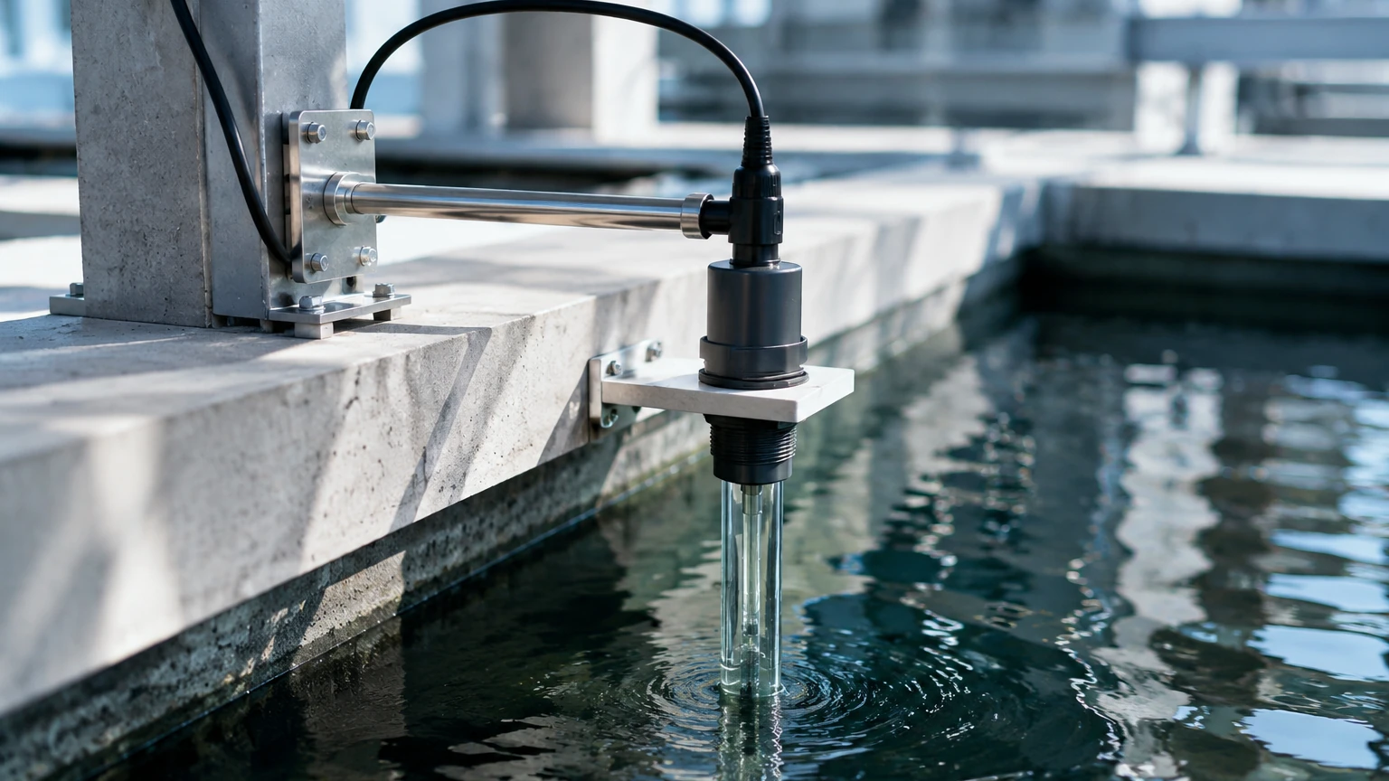
Immersion assemblies are used in open channels, basins, or tanks. The sensor is mounted at the end of a long pipe or rod, extending into the liquid.
* Depth: The sensor should be submerged deep enough to represent the bulk liquid but at least 150 mm above the bottom of the tank to avoid sediment buildup.
* Stability: In agitated tanks, the immersion assembly must be braced to prevent vibration or mechanical stress on the sensor body.
3. Bypass or Flow-Cell Installation
In this configuration, a small portion of the process liquid is diverted through a bypass line into a flow cell containing the pH sensor. This is the preferred method for high-pressure or high-temperature lines where a sample can be cooled or depressurized before measurement.
* Drainage: The flow cell should be designed to remain full of liquid even when the process flow stops, preventing the sensor bulb from drying out.
Step-by-Step Installation Procedure
Successful installation of ph meter systems requires a systematic approach to ensure electrical integrity and chemical safety.
Step 1: Pre-Installation Inspection
Inspect the sensor for cracks in the glass bulb or leakage of the electrolyte. Ensure the protective cap, which contains storage solution (usually 3M or 4M KCl), is still in place and the bulb is wet. A dry pH bulb may require 24 hours of soaking before it can be calibrated.
Step 2: Mechanical Assembly
Mount the sensor into its housing (immersion, flow-cell, or retractable). Use appropriate sealing materials, such as PTFE tape or O-rings compatible with the process chemicals. Ensure all fittings are tightened to prevent leaks, but avoid over-tightening which can crack plastic housings.
Step 3: Electrical Wiring
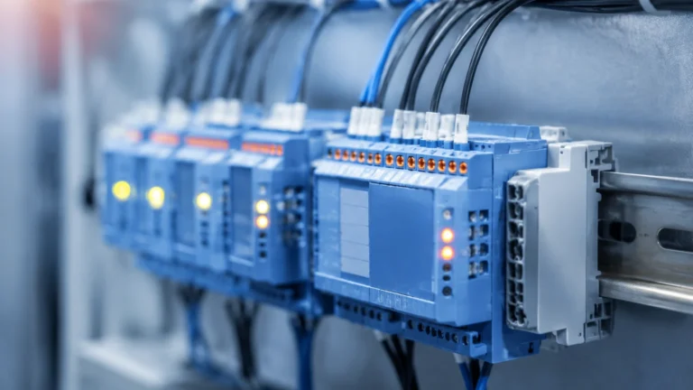
pH sensors generate a high-impedance signal (often exceeding 100 MΩ). This makes the signal extremely susceptible to electromagnetic interference (EMI).
* Cable Routing: Use specialized low-noise coaxial cables. Do not run pH signal cables in the same conduit as high-voltage power lines or variable frequency drive (VFD) cables.
* Distance Limits: Without a pre-amplifier, the distance between the sensor and the transmitter should generally not exceed 15 meters (approx. 50 feet). For longer distances, a digital sensor or an integrated pre-amplifier is required.
* Grounding: Ensure the transmitter is properly grounded. In some plastic piping systems, a solution ground (liquid earth) electrode is necessary to eliminate ground loop interference.
Step 4: Calibration
Before the final insertion into the process, perform a two-point calibration using certified buffer solutions (typically pH 4.0, 7.0, or 10.0).
1. Rinse the sensor with deionized water.
2. Place it in the pH 7.0 buffer (Neutral Point).
3. Adjust the transmitter to match the buffer value.
4. Rinse again and place in the second buffer (Slope Point).
5. Verify the slope is within 90% to 105% of the theoretical Nernstian value.
Operational Limitations and Considerations
While industrial pH meters are robust, several factors can limit their accuracy or lifespan:
* Temperature Extremes: High temperatures accelerate the aging of the glass membrane and the depletion of the reference electrolyte. For every 10°C increase in temperature, the life of a pH electrode is roughly halved.
* Pressure Fluctuations: High process pressure can force process liquid into the reference junction (poisoning the electrode) or cause the electrolyte to leak out rapidly. In these cases, pressurized reference electrodes or solid-state sensors are required.
* Coating and Fouling: In applications like wastewater or chemical precipitation, solids can coat the sensor bulb. Regular cleaning with diluted acid or specialized detergents is necessary. Some installations utilize automated ultrasonic or water-jet cleaning systems.
* Chemical Compatibility: Hydrofluoric acid (HF) will dissolve glass pH bulbs even at low concentrations. For HF applications, specialized antimony electrodes or ISFET sensors must be used.
Frequently Asked Questions (FAQ)
Q: How often should a pH meter be calibrated after installation?
A: Calibration frequency depends on the process conditions. In stable, clean water applications, monthly calibration may suffice. In harsh chemical processes or high-fouling environments, weekly or even daily calibration might be necessary.
Q: Can I use a standard PVC pipe for the installation of ph meter sensors?
A: PVC is acceptable for many water and dilute acid applications at ambient temperatures. However, for temperatures exceeding 60°C or for aggressive solvents, CPVC, PVDF, or Stainless Steel housings should be used.
Q: Why does my pH reading drift immediately after installation?
A: This is often due to temperature equilibration or static charge. Ensure the sensor has reached the process temperature and that the cable shielding is correctly terminated at the transmitter.
Q: What is the typical lifespan of an industrial pH sensor?
A: In moderate conditions, a sensor typically lasts 12 to 24 months. In extreme high-temperature or highly alkaline conditions, the lifespan may be reduced to 3 to 6 months.
Conclusion
The installation of ph meter systems is a critical task that bridges the gap between laboratory chemistry and industrial engineering. By understanding the Nernstian principle, selecting the appropriate mounting configuration, and adhering to strict electrical shielding practices, facilities can ensure reliable and accurate process data. For engineers looking to integrate pH monitoring with other liquid management technologies, exploring the Main Page of professional instrumentation providers offers a broader perspective on automated process control solutions.