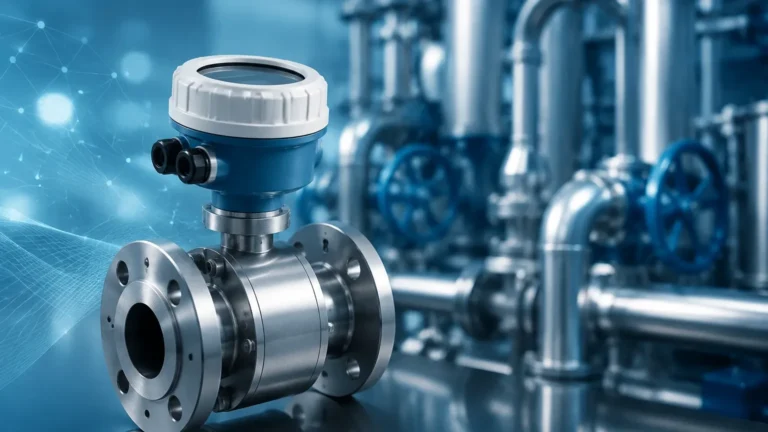
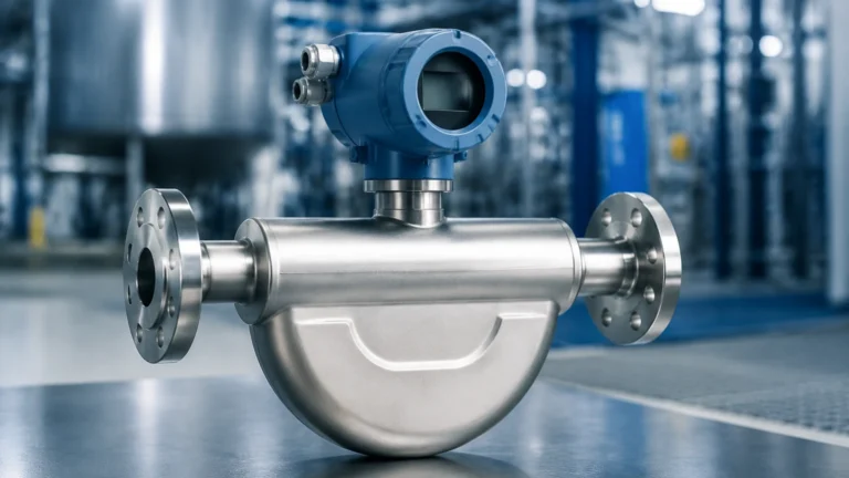
Inline Flow Sensor
Inline Flow Sensor
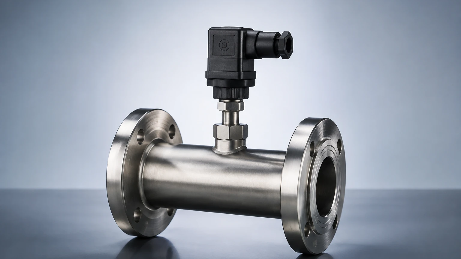
In the landscape of industrial process control, the inline flow sensor stands as a fundamental component for monitoring the movement of liquids and gases through a piping system. Unlike non-invasive methods, an inline flow sensor is integrated directly into the process line, becoming a physical part of the fluid path. This direct contact allows for high-precision data acquisition, which is critical for applications ranging from chemical dosing and water treatment to oil and gas distribution.
Selecting the correct flow measurement technology requires a deep understanding of fluid dynamics, material compatibility, and the specific mechanical constraints of the installation site. For engineers and facility managers, the integration of flow data with level measurement systems—such as those found on the Welk Main Page—provides a comprehensive view of mass balance and inventory management within a facility.
Core Measurement Principles of Inline Flow Sensors
Before selecting an inline flow sensor, it is essential to understand the physical principles that govern different sensor types. No single technology is universal; each has strengths and limitations based on the fluid's properties.
Electromagnetic Flow Measurement
Electromagnetic sensors, often called "magmeters," operate based on Faraday’s Law of Induction. When a conductive liquid flows through a magnetic field generated by the sensor, it creates a voltage proportional to the velocity of the fluid.
* Requirement: The fluid must be electrically conductive (typically >5 μS/cm).
* Advantage: There are no moving parts or obstructions in the flow path, resulting in zero pressure drop and minimal maintenance.
Thermal Dispersion
Thermal inline flow sensors measure the mass flow of gases or liquids by detecting the rate of heat dissipation from a heated sensing element. As the fluid moves past the sensor, it carries heat away; the faster the flow, the greater the cooling effect.
* Requirement: Best suited for clean gases and low-viscosity liquids.
* Advantage: High sensitivity to low flow rates and direct mass flow measurement without needing separate pressure or temperature compensation.
Ultrasonic Transit-Time
While ultrasonic sensors are often associated with external clamp-on designs, inline versions utilize transducers mounted within a flow tube. These sensors measure the time difference between ultrasonic pulses traveling upstream and downstream.
* Requirement: The fluid should be relatively clean and free of excessive bubbles or solids that could scatter the signal.
* Advantage: High accuracy and the ability to handle a wide range of pipe sizes, from 15 mm (0.5 inches) to over 2,000 mm (80 inches).
Vortex Shedding
Vortex sensors utilize a "shedder bar" placed in the flow stream. As fluid hits the bar, it creates alternating vortices (swirls) downstream. The frequency of these vortices is directly proportional to the flow velocity.
* Requirement: Sufficient Reynolds number (turbulent flow) is necessary for the vortices to form consistently.
* Advantage: Excellent for steam measurement and high-temperature applications.
Key Selection Criteria for Industrial Applications
Choosing an inline flow sensor involves evaluating the process environment against the sensor's technical specifications. Engineers should prioritize the following factors:
1. Fluid Characteristics
* Viscosity: High-viscosity fluids like heavy oils may require positive displacement or Coriolis meters, as vortex or turbine meters may lose accuracy.
* Conductivity: If the fluid is non-conductive (e.g., deionized water or hydrocarbons), electromagnetic sensors cannot be used.
* Corrosiveness: The wetted parts of the sensor must be compatible with the process media. Common materials include 316L stainless steel, Hastelloy, or PTFE liners.
2. Flow Range and Turndown Ratio
The turndown ratio defines the range over which the sensor can measure accurately. For example, a sensor with a 10:1 turndown ratio and a maximum flow of 100 m³/h (440 GPM) can accurately measure down to 10 m³/h (44 GPM). If your process requires measuring very low leak rates and high peak flows, a high turndown ratio is essential.
3. Operating Temperature and Pressure
Standard inline flow sensors are typically rated for temperatures up to 150°C (302°F), but specialized versions for steam or cryogenic fluids are required for extreme ranges. Similarly, the flange rating (e.g., PN16, PN40, or ANSI 150/300) must match the system's maximum operating pressure.
Installation Considerations and Best Practices
The accuracy of an inline flow sensor is heavily dependent on how it is installed. Even the most expensive sensor will provide erroneous data if the flow profile is disturbed.
Straight Pipe Requirements
Most sensors require a specific length of straight pipe upstream and downstream to ensure a stable, laminar flow profile. A common rule of thumb is "10D Upstream and 5D Downstream," meaning the straight pipe should be ten times the pipe diameter before the sensor and five times the diameter after it. If elbows, valves, or pumps are located near the sensor, these requirements may increase to 20D or 30D.
Pipe Orientation
* Horizontal Lines: This is the most common orientation. For liquid applications, the pipe must remain full. For gas applications, the sensor should be placed to avoid moisture accumulation.
* Vertical Lines: When measuring liquids, the flow should always be upward. This ensures the pipe remains full and prevents air pockets from forming at the sensor head.
Grounding and Interference
For electromagnetic sensors, proper grounding is critical. The sensor must be at the same electrical potential as the fluid to prevent stray currents from interfering with the low-voltage signal generated by the flow. In plastic piping systems, grounding rings are required to establish this connection.
Technical Comparison Table
| Sensor Type | Fluid Phase | Accuracy (Typical) | Pressure Drop | Moving Parts |
| :— | :— | :— | :— | :— |
| Electromagnetic | Conductive Liquid | ±0.5% | None | No |
| Ultrasonic | Liquid / Gas | ±1.0% | None | No |
| Vortex | Liquid / Gas / Steam | ±1.0% | Medium | No |
| Thermal | Gas / Clean Liquid | ±1.0% to 2.0% | Low | No |
| Turbine | Clean Liquid / Gas | ±0.25% to 0.5% | High | Yes |
Limitations and Common Operational Risks
While an inline flow sensor provides reliable data, certain conditions can compromise performance:
1. Entrained Air and Cavitation: In liquid lines, bubbles or air pockets can cause significant measurement errors, especially in ultrasonic and electromagnetic meters. Cavitation—the formation and collapse of vapor bubbles due to pressure drops—can also damage the sensor internals.
2. Scaling and Buildup: In wastewater or chemical processing, minerals or biological matter can build up on the sensor electrodes or the inner wall of the flow tube. This changes the effective diameter of the pipe and leads to "drift" in accuracy over time.
3. Vibration: High-frequency mechanical vibration from nearby pumps or compressors can interfere with vortex and ultrasonic sensors. Using flexible couplings or dedicated pipe supports can mitigate this risk.
4. Minimum Flow Velocity: Most sensors have a minimum velocity threshold (often around 0.3 m/s or 1 fps). Below this point, the signal-to-noise ratio becomes too low for reliable measurement.
Frequently Asked Questions (FAQ)
Can an inline flow sensor measure bidirectional flow?
Yes, many modern electromagnetic and ultrasonic sensors are designed to measure flow in both directions. This is particularly useful in water distribution networks where backflow monitoring is required. However, the installation must still meet straight-run requirements for both directions.
How often should a flow sensor be calibrated?
Calibration frequency depends on the criticality of the process and the nature of the fluid. For regulated industries like pharmaceuticals or food and beverage, annual calibration is standard. For general industrial water monitoring, a check every 2-3 years may suffice unless drift is detected.
What is the difference between a flow meter and a flow sensor?
Technically, a "sensor" is the element that detects the flow, while a "meter" includes the sensor, the transmitter, and the display. In modern B2B contexts, the terms are often used interchangeably to describe the complete assembly installed in the line.
Why is my electromagnetic flow sensor showing an erratic reading?
Erratic readings in magmeters are often caused by improper grounding, a partially filled pipe, or the presence of air bubbles. Ensure the sensor is installed in a vertical upward-flow section or a low point in a horizontal run to guarantee a full pipe.
Conclusion
The integration of a high-quality inline flow sensor is a prerequisite for precision in modern industrial automation. By understanding the underlying physics—whether electromagnetic, ultrasonic, or thermal—and adhering to strict installation guidelines regarding pipe runs and fluid compatibility, engineers can ensure long-term reliability. For comprehensive process control, these flow solutions are most effective when paired with robust level measurement technologies, creating a unified data environment for plant operations. For more information on integrated measurement solutions, professionals can review the technical resources available on the Main Page of industry-leading manufacturers.