Inline Flowmeters
Inline Flowmeters
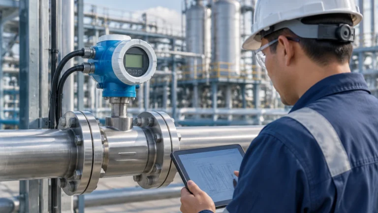
In the landscape of industrial process automation, the ability to quantify the movement of liquids, gases, and steam within a closed conduit is fundamental to operational efficiency and safety. Inline flowmeters represent a broad category of instrumentation designed to be integrated directly into a piping system to provide real-time data on flow rates. While level measurement instruments, such as those featured on the Main Page, provide critical data regarding the volume of media stored in tanks and vessels, inline flowmeters serve as the dynamic counterpart, monitoring the transit of that media through the process chain.
Selecting the appropriate inline flowmeter requires a deep understanding of fluid dynamics, material compatibility, and the specific physical principles that govern different measurement technologies. This guide provides a technical overview of inline flow measurement, selection criteria, and installation best practices for engineering professionals.
Core Measurement Principles of Inline Flowmeters
Inline flowmeters are categorized by the physical principle they employ to determine the velocity or mass of the fluid. Each technology has specific strengths and limitations based on the state and properties of the media.
Electromagnetic Flowmeters (Magmeters)
Electromagnetic flowmeters operate based on Faraday’s Law of Electromagnetic Induction. This principle states that a conductor (the fluid) moving through a magnetic field generates an electrical voltage. In an inline magmeter, the flow tube is equipped with electromagnetic coils that generate a field and electrodes that detect the induced voltage.
Because the voltage is directly proportional to the flow velocity, these meters are highly accurate for conductive liquids. Since there are no moving parts or obstructions in the flow path, they result in zero pressure drop and are ideal for slurries and corrosive chemicals. However, they cannot measure non-conductive fluids like oils or deionized water.
Ultrasonic Inline Flowmeters
Ultrasonic meters typically use the transit-time principle. Two transducers are mounted in the flow tube, sending and receiving ultrasonic signals. When the fluid is moving, the signal traveling with the flow moves faster than the signal traveling against it. The difference in time is used to calculate the flow velocity.
Inline ultrasonic meters are preferred for clean liquids and are often used in water treatment and HVAC applications. Unlike clamp-on versions, inline ultrasonic meters are factory-calibrated with the flow tube, ensuring higher precision and stability over time.
Coriolis Mass Flowmeters
Coriolis meters are unique because they measure mass flow directly rather than volume. They consist of one or more vibrating tubes. As fluid flows through the vibrating tube, it induces a Coriolis force that causes the tube to twist or shift in phase. This phase shift is directly proportional to the mass flow rate.
These instruments are considered the "gold standard" for accuracy in the chemical and oil and gas industries. They are unaffected by changes in fluid density, pressure, or viscosity, and can simultaneously measure density and temperature.
Vortex Flowmeters
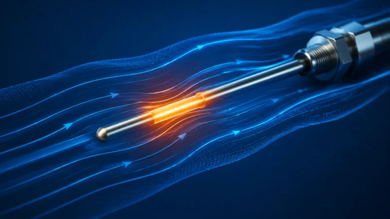
Vortex meters utilize the Von Kármán effect. When a fluid encounters a "shedder bar" placed in the flow stream, it creates alternating vortices (swirls). The frequency at which these vortices are shed is directly proportional to the flow velocity.
Vortex meters are robust and versatile, commonly used for measuring steam, high-temperature gases, and low-viscosity liquids. They have no moving parts, which reduces maintenance requirements in harsh environments.
Turbine Flowmeters
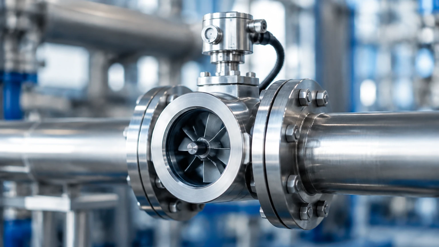
Turbine meters use a multi-bladed rotor suspended in the flow stream. As the fluid passes through, it causes the rotor to spin at a speed proportional to the flow velocity. A pickup coil or sensor detects the rotation of the blades. These are highly effective for clean, low-viscosity liquids and gases where high precision is required at a lower cost than Coriolis technology.
Selection Criteria for Industrial Applications
Choosing the right inline flowmeter is not a "one size fits all" process. Engineers must evaluate several variables to ensure long-term reliability and accuracy.
Fluid Properties
* Conductivity: Required for electromagnetic meters (typically >5 μS/cm).
* Viscosity: High-viscosity fluids may require Coriolis or positive displacement meters, as turbine or vortex meters may lose accuracy.
* Phase: Is the media a liquid, gas, or steam? Does it contain solids or entrained air?
* Corrosivity: The wetted parts (liners and electrodes) must be compatible with the chemical makeup of the fluid.
Process Conditions
* Pressure and Temperature: Every meter has a rated pressure-temperature envelope. Vortex and Coriolis meters are generally better suited for extreme temperatures than ultrasonic or electromagnetic types.
* Flow Range (Turndown Ratio): This is the ratio between the maximum and minimum flow the meter can accurately measure. A 10:1 ratio is common, but some high-end meters offer 100:1 or more.
Accuracy and Repeatability
In B2B industrial applications, accuracy requirements vary. Custody transfer (buying/selling fluid) requires the highest accuracy (often <0.1%), whereas simple process monitoring may only require 1-2% accuracy.
Practical Selection Comparison Table
| Technology | Typical Accuracy | Fluid Type | Moving Parts | Pressure Drop | Typical Application |
| :— | :— | :— | :— | :— | :— |
| Electromagnetic | ±0.5% | Conductive Liquids | No | Negligible | Water, Slurries, Chemicals |
| Ultrasonic (Inline) | ±0.5% to 1.0% | Clean Liquids | No | Negligible | Chilled Water, Process Water |
| Coriolis | ±0.1% | Liquids, Gases | No | Medium | Custody Transfer, Dosing |
| Vortex | ±1.0% | Steam, Gas, Liquid | No | Medium | Steam Lines, Gas Flow |
| Turbine | ±0.25% to 0.5% | Clean, Low-Viscosity | Yes | High | Fuel, Solvents, Water |
Installation Guidelines and Best Practices
The performance of an inline flowmeter is heavily dependent on how it is installed. Even the most expensive meter will provide inaccurate data if the flow profile is disturbed.
Straight Pipe Requirements
Most inline flowmeters require a specific length of straight pipe both upstream and downstream to ensure a stable, laminar flow profile. A common rule of thumb is "10D Upstream and 5D Downstream," where D is the nominal pipe diameter. If a valve or elbow is located too close to the meter, it creates turbulence that biases the reading.
Pipe Orientation and Filling
For liquid applications, the pipe must be completely full for the meter to function correctly.
* Vertical Upward Flow: This is the preferred orientation for liquids, as it ensures the pipe remains full and prevents air pockets from forming at the sensor.
* Horizontal Flow: If installed horizontally, the electrodes in a magmeter should be positioned at the 3 o'clock and 9 o'clock positions to avoid interference from air bubbles at the top or sediment at the bottom.
* Avoid Vertical Downward Flow: This can lead to partially filled pipes or vacuum conditions, which will cause significant measurement errors.
Grounding and Interference
Electromagnetic flowmeters are sensitive to stray electrical noise. Proper grounding to the process piping (using grounding rings if the pipe is plastic or lined) is essential to ensure the millivolt signal generated by the flow is not obscured by interference.
Integration with Level Measurement Systems
In many industrial setups, inline flowmeters and level meters work in tandem to provide a complete picture of the process. This is often referred to as "Mass Balance" or "Inventory Control."
For example, in a large chemical storage tank, a radar level meter provides the static volume data. Simultaneously, an inline Coriolis or electromagnetic flowmeter on the inlet and outlet pipes tracks the dynamic movement of the product. By comparing the flow rate (the derivative of volume over time) with the actual change in level, operators can detect leaks, verify pump performance, and ensure precise dosing.
For engineers looking to integrate these technologies, reviewing comprehensive product options and application support on the Main Page is a recommended starting point to ensure that both level and flow instruments are compatible with the control architecture.
Limitations and Common Risks
While inline flowmeters are highly reliable, there are several risks that can lead to failure or inaccuracy:
1. Cavitation: If the pressure drops too low inside the meter, vapor bubbles can form and collapse. This is particularly damaging to turbine meters and can cause erratic readings in ultrasonic and vortex meters.
2. Scaling and Coating: In wastewater or chemical applications, material can build up on the inner walls or electrodes of the meter. This changes the internal diameter and affects the calibration. Regular inspection or the use of meters with "removable electrodes" may be necessary.
3. Mechanical Wear: Turbine meters have bearings that will eventually wear out, especially if the fluid contains abrasive particles. For maintenance-heavy environments, solid-state meters like magmeters or vortex meters are generally preferred.
4. Signal Damping: In applications with pulsating flow (e.g., downstream of a diaphragm pump), the meter may struggle to provide a stable reading. In these cases, pulsation dampeners or meters with high-speed digital signal processing are required.
Frequently Asked Questions (FAQs)
Q: Can inline flowmeters measure flow in both directions?
A: Many modern electromagnetic and ultrasonic flowmeters are bi-directional. They can track flow in both directions and provide separate totals for each. However, vortex and turbine meters are typically uni-directional.
Q: How often do inline flowmeters need to be calibrated?
A: Calibration frequency depends on the industry and the criticality of the measurement. In regulated industries like pharmaceuticals or food production, annual calibration is standard. In general industrial water use, a check every 2-3 years may suffice unless a shift in accuracy is noted.
Q: What is the difference between a full-bore and an insertion flowmeter?
A: An inline (full-bore) flowmeter replaces a section of the pipe and measures the entire stream. An insertion meter is a small probe inserted through a hole in the pipe wall. Inline meters are significantly more accurate because they account for the entire flow profile, whereas insertion meters only measure a single point and calculate the rest.
Q: Do I need a strainer before my flowmeter?
A: For turbine and some ultrasonic meters, a strainer is highly recommended to prevent debris from damaging the internal components or blocking the ultrasonic path. For magmeters with a clear bore, a strainer is usually unnecessary.
Conclusion
Inline flowmeters are essential tools for modern industrial processes, providing the data necessary for precise control, billing, and safety. By understanding the underlying measurement principles—from electromagnetic induction to Coriolis forces—engineers can select the technology that best fits their specific fluid properties and environmental constraints. When combined with robust level measurement solutions, these instruments form the backbone of a reliable process automation system. For further technical specifications and to explore a range of measurement instruments, visit the Main Page to find solutions tailored to your specific application requirements.