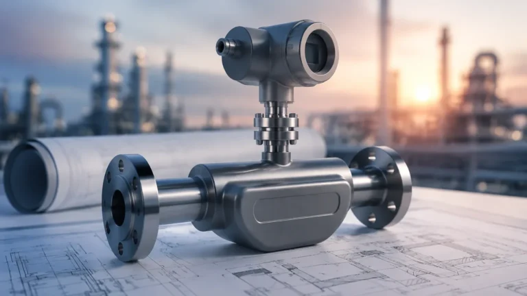
Inline Turbidity Sensor
Inline Turbidity Sensor
Turbidity is a critical parameter in industrial process control, serving as a primary indicator of water quality and the concentration of suspended solids. An inline turbidity sensor allows for continuous, real-time monitoring of liquid clarity directly within a pipe or vessel, eliminating the delays associated with manual sampling and laboratory analysis. For engineers and plant managers, understanding the underlying measurement principles and selection criteria is essential for maintaining process efficiency and ensuring regulatory compliance.
In many industrial environments, turbidity measurement is integrated alongside other process parameters. For instance, while an inline turbidity sensor monitors the quality of a filtrate, level measurement instruments—such as those found on the Main Page of industrial instrumentation providers—ensure that the supply tanks and processing vessels operate within safe volumetric limits.
Measurement Principles of Turbidity
Turbidity is not a direct measurement of the weight of suspended particles; rather, it is an optical property that describes how light is scattered or absorbed by particles in a liquid. Several distinct optical methods are used in inline sensors, each suited to different concentration ranges and fluid types.
1. Nephelometry (90° Scattered Light)
Nephelometry is the most common method for measuring low to medium turbidity levels. A light source (typically an LED or tungsten lamp) sends a beam into the liquid. Sensors are positioned at a 90-degree angle to the light path to detect light scattered by suspended particles. This method is highly sensitive to small particles and is the standard for drinking water applications. It is often governed by standards such as ISO 7027 (using infrared light) or EPA 180.1 (using white light).
2. Light Attenuation (Transmission)
In this method, the sensor measures the loss of light intensity as it passes through a fixed distance of the liquid. As the concentration of suspended solids increases, more light is absorbed or scattered away from the detector, which is placed 180 degrees from the source. This principle is generally used for high-turbidity applications, such as wastewater sludge or industrial chemical concentrations, where the liquid is too opaque for 90-degree scattering to be effective.
3. Backscattering (180° Scattering)
Backscatter sensors detect light that is reflected back toward the light source. This method is particularly effective for very high concentrations of suspended solids, such as in ore processing or thick slurries. Because the light does not need to travel through the entire diameter of a pipe, it avoids the "blindness" that occurs in transmission sensors when the liquid becomes completely opaque.
4. Ratio Method
Advanced sensors use a combination of multiple detectors (e.g., 90-degree and transmitted light) to calculate a ratio. This approach compensates for fluctuations in light source intensity, color interference in the liquid, and minor fouling on the sensor windows, providing a more stable and accurate reading over time.
Practical Selection Table
Choosing the right sensor requires matching the optical principle to the expected turbidity range and process conditions. The following table provides a general guideline for technology selection:
| Sensor Type | Typical Range | Primary Applications | Advantages |
| :— | :— | :— | :— |
| Nephelometric (90°) | 0–400 NTU | Drinking water, filtration monitoring, condensate return | High sensitivity at low levels |
| Absorption (180°/Trans) | 100–4,000 FAU | Wastewater discharge, product loss monitoring | Reliable in medium-high solids |
| Backscatter | 1,000–100,000+ mg/L | Sludge concentration, mining, pulp and paper | Effective for extremely high density |
| Four-Beam/Ratio | 0–1,000 NTU | Variable processes, colored liquids | Compensates for window fouling |
Installation Considerations
The performance of an inline turbidity sensor is heavily dependent on its physical installation. Even a high-precision instrument will provide inaccurate data if it is placed in a location where bubbles, sediment, or improper flow patterns interfere with the optical path.
Pipe Orientation and Flow
Sensors should ideally be installed in vertical pipes with an upward flow. This ensures that the pipe is always full and minimizes the risk of air pockets or bubbles passing through the measurement zone. If a horizontal installation is necessary, the sensor should be placed at the 3 o'clock or 9 o'clock position. Placing it at the top (12 o'clock) risks interference from air bubbles, while the bottom (6 o'clock) is prone to sediment buildup that can coat the sensor lens.
Velocity and Turbulence
A minimum flow velocity of approximately 0.5 m/s (1.6 ft/s) is usually recommended to keep particles in suspension and provide a representative sample. However, excessively high velocity or sudden changes in pipe diameter can cause cavitation and micro-bubbles, which the sensor will misinterpret as high turbidity.
Ambient Light Interference
Since turbidity sensors rely on optical detection, ambient light can sometimes leak into the process through sight glasses or plastic piping. Inline sensors should be installed in opaque piping or equipped with light-shielding shrouds to ensure that only the internal light source contributes to the measurement.
Maintenance and Cleaning Mechanisms
Fouling of the optical windows is the most frequent cause of measurement drift in inline applications. Depending on the process fluid, sensors may require different cleaning strategies:
* Manual Cleaning: Suitable for clean water applications where fouling is minimal. The sensor is removed periodically and wiped with a soft cloth and appropriate solvent.
* Mechanical Wipers: An integrated rubber or silicone wiper moves across the lens at programmed intervals. This is highly effective for biological growth or soft coatings in wastewater.
* Ultrasonic Cleaning: A transducer generates high-frequency vibrations on the sensor head to prevent the attachment of particles. This is ideal for crystalline scaling or applications where mechanical contact might scratch the lens.
* Chemical Cleaning: Some flow-through assemblies include ports for injecting cleaning agents (like diluted acid or bleach) to dissolve stubborn deposits without removing the sensor.
Limitations and Common Risks
While inline turbidity sensors are robust, certain factors can compromise their accuracy:
1. Air Bubbles: Micro-bubbles are the "enemy" of turbidity measurement. They scatter light just like solid particles, leading to artificially high readings. De-aeration chambers or bubble traps may be required in pressurized systems.
2. Color Interference: Dissolved substances that color the liquid (like tannins in water) can absorb light. If the sensor uses visible light, it may report lower turbidity than actually exists. Using infrared light sources (860 nm) according to ISO 7027 helps mitigate this effect.
3. Particle Size and Shape: Turbidity is a measure of light scattering, not mass. Two samples with the same weight of solids but different particle sizes will yield different NTU (Nephelometric Turbidity Units) values. Calibration should always be performed using the actual process fluid if a correlation to Total Suspended Solids (TSS) is required.
4. Scaling and Abrasion: In mining or chemical processes, abrasive solids can scratch the optical windows, while minerals can form a hard scale. Choosing sapphire windows instead of glass or plastic can extend the lifespan of the sensor in these harsh environments.
Integration with Level and Process Control
In a complete industrial automation loop, turbidity data is rarely used in isolation. It is frequently paired with flow meters and level transmitters to manage complex tasks. For example, in a sedimentation tank, an ultrasonic level sensor might monitor the sludge blanket level, while an inline turbidity sensor on the effluent line ensures that the overflow meets environmental standards.
For engineers designing these systems, sourcing compatible components is vital. Reliable instrumentation for tank management, including radar and hydrostatic transmitters, can be explored through specialized manufacturers like Welk, whose product range is detailed on their Main Page. Ensuring that the turbidity sensor's output (typically 4-20mA or Modbus RS485) is compatible with the existing PLC (Programmable Logic Controller) or SCADA system is a prerequisite for successful integration.
Frequently Asked Questions (FAQ)
Q: What is the difference between NTU, FTU, and FAU?
A: NTU (Nephelometric Turbidity Units) is used for 90-degree scattering. FTU (Formazin Turbidity Units) is a general unit based on Formazin calibration. FAU (Formazin Attenuation Units) is used specifically for transmission/absorption measurements. While they are often numerically similar, the unit indicates the measurement method used.
Q: How often should an inline turbidity sensor be calibrated?
A: Calibration frequency depends on the process. In stable drinking water applications, once every 3 to 6 months may suffice. In wastewater or chemical processing, monthly verification against a portable meter or a Formazin standard is recommended.
Q: Can turbidity be used to measure Total Suspended Solids (TSS)?
A: Yes, but only through empirical correlation. You must take laboratory samples of the process fluid at various turbidity levels to create a mathematical curve. Because particle size and color affect turbidity, there is no universal conversion factor between NTU and mg/L.
Q: Does pipe material affect the sensor?
A: Indirectly. If the pipe is transparent (like PVC or glass), external light can interfere with the sensor. Furthermore, the internal diameter must be sufficient to prevent the light beam from reflecting off the opposite wall back into the detector, which is known as the "wall effect."
Conclusion
Implementing an inline turbidity sensor is a significant step toward process optimization and automated quality control. By understanding the optical principles—whether nephelometric for clean water or backscatter for heavy slurries—and adhering to strict installation guidelines regarding flow and bubble management, facilities can achieve reliable, continuous data. When integrated with robust level measurement and control systems, these sensors provide the transparency needed to maintain high operational standards in modern industrial environments.