Inline Water Flow Sensor
Inline Water Flow Sensor
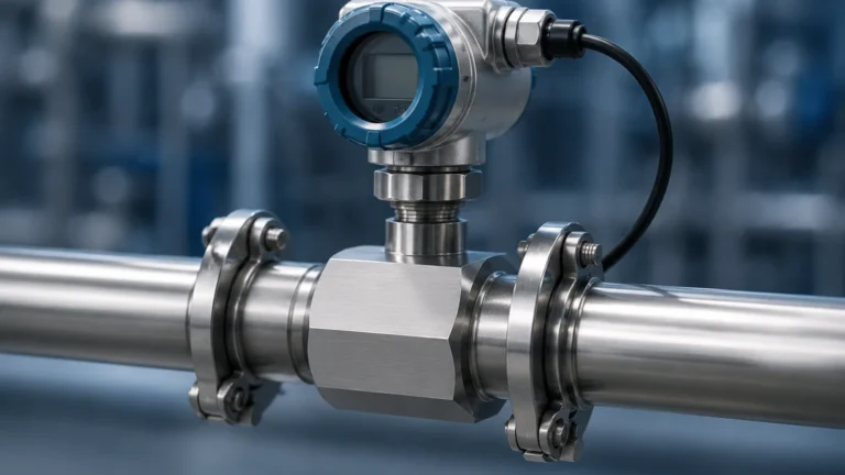
In industrial process control and water management, the inline water flow sensor serves as a critical component for monitoring consumption, managing distribution, and ensuring the efficiency of automated systems. Unlike non-invasive clamp-on meters, an inline sensor is integrated directly into the piping circuit, becoming a physical part of the conduit. This configuration allows for direct contact with the medium, often resulting in higher sensitivity and faster response times for dynamic flow conditions.
Selecting the appropriate inline water flow sensor requires a deep understanding of fluid dynamics, material compatibility, and the specific requirements of the application, whether it involves municipal water treatment, chemical processing, or industrial cooling loops.
Common Measurement Principles for Inline Water Flow Sensors
Inline flow measurement is not a one-size-fits-all technology. Several distinct physical principles are employed depending on the water's purity, conductivity, and the required precision.
1. Electromagnetic Flow Meters (Magmeters)
Electromagnetic sensors operate based on Faraday’s Law of Electromagnetic Induction. This principle states that a conductor (in this case, conductive water) moving through a magnetic field produces an electrical voltage. The voltage generated is directly proportional to the velocity of the water flowing through the pipe.
* Advantages: No moving parts, zero pressure drop, and high accuracy (typically ±0.5%).
* Requirement: The water must have a minimum conductivity, usually >5 μS/cm. This makes them ideal for raw water, wastewater, and process water, but unsuitable for deionized or distilled water.
2. Turbine Flow Sensors
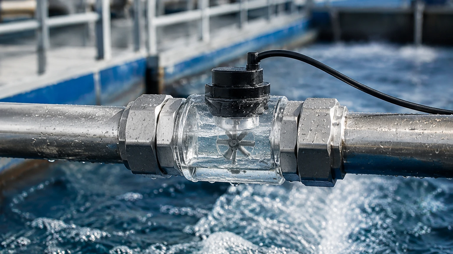
Turbine sensors utilize a multi-bladed rotor mounted on bearings within the flow stream. As water passes through the sensor body, it forces the rotor to spin. The rotational speed is proportional to the flow velocity. A magnetic pickup or Hall effect sensor detects the passage of the rotor blades and converts this into a frequency or pulse signal.
* Advantages: Excellent repeatability and high-speed response.
* Limitations: Mechanical parts are subject to wear. They are sensitive to suspended solids, which can clog the rotor or erode the bearings. They are best suited for clean, filtered water.
3. Ultrasonic Inline Sensors (Transit-Time)
While ultrasonic meters are often associated with clamp-on designs, inline versions feature factory-aligned transducers within a spool piece. These sensors measure the time difference between ultrasonic pulses traveling upstream and downstream. The difference in transit time is used to calculate the flow velocity.
* Advantages: No moving parts and negligible pressure drop. They can handle a wide range of temperatures and are highly accurate across a broad turndown ratio.
* Limitations: Generally more expensive than turbine meters and requires the water to be free of significant aeration or heavy bubble concentrations.
4. Vortex Flow Sensors
Vortex shedding sensors place a "bluff body" (a non-streamlined object) in the flow path. As water flows past this body, vortices are shed alternately on each side. The frequency of these vortices is directly proportional to the flow velocity.
* Advantages: Robust design with no moving parts. Excellent for high-temperature water and steam applications.
* Limitations: Requires a minimum Reynolds number to function; at very low flow rates, the vortices are too weak to be detected.
Technical Selection Criteria
When specifying an inline water flow sensor for a B2B project, engineers must evaluate several technical parameters to ensure long-term reliability and data integrity.
Pipe Size and Flow Range
The nominal diameter of the pipe (DN) and the expected flow velocity are the primary starting points. It is a common mistake to simply match the sensor size to the existing pipe size. However, if the flow velocity is too low for the sensor's range, accuracy will suffer. Conversely, a sensor that is too small will create a significant pressure drop and may be damaged by high-velocity cavitation.
Material Compatibility
The sensor body and internal wetted parts (electrodes, liners, or rotors) must be compatible with the water chemistry.
* Standard Potable Water: Stainless steel 316 or high-grade plastics (PVC/PVDF) are common.
* Demineralized Water: Requires non-leaching materials to maintain water purity.
* Brackish or Saline Water: May require Hastelloy electrodes or specialized liners to prevent corrosion.
Output Signals and Integration
Modern industrial environments require the sensor to communicate with a PLC (Programmable Logic Controller) or SCADA system. Common outputs include:
* 4-20mA Analog: Standard for continuous flow rate monitoring.
* Pulse/Frequency: Ideal for totalization (measuring total volume over time).
* Digital Protocols: Modbus RTU, HART, or Profibus for advanced diagnostics and multi-parameter data.
For complex installations where flow data must be synchronized with tank levels or pressure readings, engineers can Review product options and application support to find integrated solutions that bridge the gap between flow and level measurement.
Installation Best Practices
The performance of an inline water flow sensor is heavily dependent on its physical installation. Turbulence is the primary enemy of accuracy.
Straight Pipe Requirements
Most inline sensors require a specific length of straight pipe upstream and downstream of the installation point to ensure a stable, laminar flow profile.
* Upstream: Typically 10 to 20 times the pipe diameter (10D – 20D).
* Downstream: Typically 5 times the pipe diameter (5D).
If elbows, valves, or pumps are located too close to the sensor, the resulting turbulence will cause erratic readings.
Orientation and Air Pockets
* Horizontal Pipes: The sensor should be installed in a section of the pipe that is always full. Avoid high points where air can trap, as air bubbles will cause significant errors in electromagnetic and ultrasonic sensors.
* Vertical Pipes: For the best results, water should flow upward through the sensor. This ensures the pipe remains full and prevents air from settling in the measurement zone.
Grounding (For Electromagnetic Sensors)
Magmeters measure very small voltages. To prevent electrical noise from interfering with the measurement, the sensor must be properly grounded to the fluid. In plastic piping systems, this often requires the installation of grounding rings on either side of the sensor.
Operational Limitations and Maintenance
While inline sensors are designed for industrial durability, they are not immune to environmental and process-related challenges.
1. Scaling and Fouling: In hard water applications, calcium carbonate or other minerals can build up on the internal walls or electrodes. This changes the internal diameter or insulates the electrodes, leading to drift. Periodic cleaning or the use of sensors with "self-cleaning" electrode designs may be necessary.
2. Pressure Drop: Mechanical sensors like turbine or paddlewheel meters introduce a physical obstruction. In gravity-fed systems or low-pressure loops, this pressure drop must be calculated to ensure it does not impede the process.
3. Cavitation: If the pressure at the sensor drops below the vapor pressure of the water, vapor bubbles form and collapse. This can physically pit the sensor internals and cause massive measurement errors.
Selection Comparison Table
| Sensor Type | Ideal Water Type | Accuracy | Pressure Drop | Moving Parts | Typical Application |
| :— | :— | :— | :— | :— | :— |
| Electromagnetic | Conductive / Wastewater | High (±0.5%) | None | No | Municipal Water, Slurries |
| Turbine | Clean / Deionized | High (±1.0%) | Medium | Yes | Cooling Loops, Batching |
| Ultrasonic | Clean / Treated | High (±1.0%) | None | No | Large Diameter Mains |
| Vortex | High Temp / Steam | Moderate (±1.5%) | Low | No | Boiler Feedwater |
| Paddlewheel | General Purpose | Moderate (±2-5%) | Low | Yes | Irrigation, Pool Systems |
Frequently Asked Questions
Q: Can an inline water flow sensor measure flow in both directions?
A: Some technologies, such as electromagnetic and transit-time ultrasonic meters, are inherently bi-directional. However, they must be configured in the software to provide separate totals for forward and reverse flow. Mechanical turbine meters are generally uni-directional.
Q: How often should an inline sensor be calibrated?
A: For most industrial applications, an annual calibration check is recommended. In highly regulated industries like pharmaceutical or food production, semi-annual calibration may be required. If the water contains abrasives or corrosive chemicals, more frequent checks are necessary to account for physical wear.
Q: What happens if the pipe is only partially full?
A: Most standard inline flow sensors will provide highly inaccurate data if the pipe is not 100% full. For partially filled pipes (such as in gravity-fed sewers), specialized "partially full" magmeters or area-velocity sensors must be used.
Q: Is a strainer required before the sensor?
A: For turbine and paddlewheel sensors, a strainer is mandatory to prevent solids from damaging the moving parts. For electromagnetic or vortex meters, a strainer is usually not required unless the solids are large enough to physically block the pipe.
By understanding these technical nuances, procurement and engineering teams can select an inline water flow sensor that provides accurate data throughout the lifecycle of the industrial system. For more information on how flow measurement integrates with broader level and inventory management systems, visit the Main Page for detailed technical specifications and product ranges.