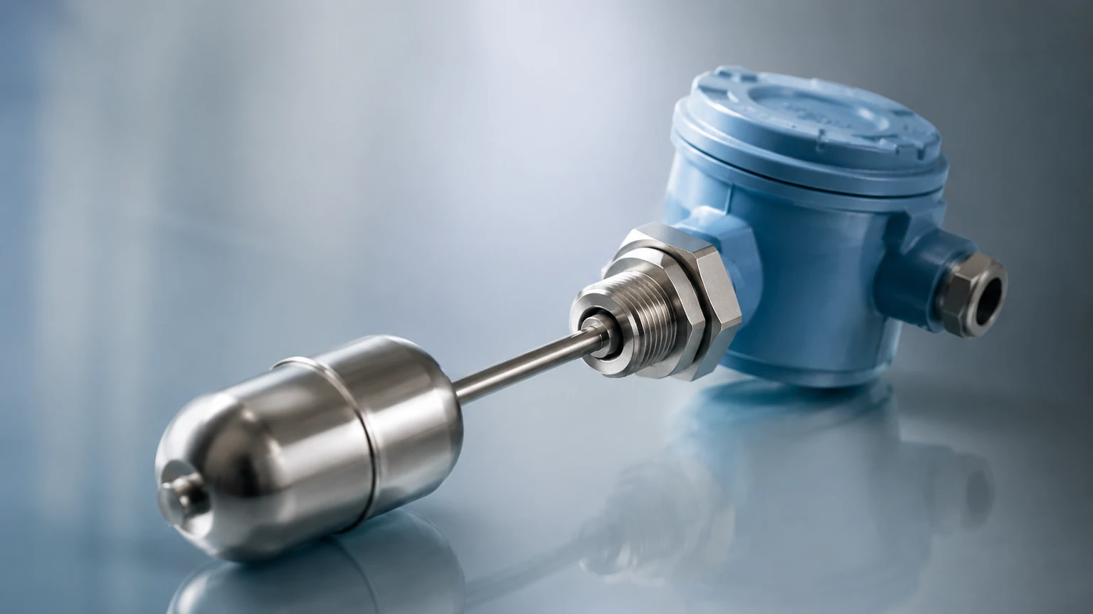
Intrinsically Safe Float Switch
Intrinsically Safe Float Switch
In industrial environments where flammable gases, vapors, or combustible dusts are present, electrical equipment must be designed to prevent ignition. Level control is a fundamental requirement in these settings, particularly in oil and gas, chemical processing, and wastewater treatment. An intrinsically safe float switch provides a reliable, low-cost solution for point-level detection while adhering to strict explosion-protection standards. By limiting the electrical energy available to a level that cannot ignite a specific hazardous atmosphere, these devices ensure operational safety without the need for heavy, expensive explosion-proof housings.
Understanding the Measurement Principle
The operation of a float switch is rooted in the principle of buoyancy, or Archimedes' Principle, which states that any object, wholly or partially immersed in a fluid, is buoyed up by a force equal to the weight of the fluid displaced by the object.
In a practical industrial application, the float switch consists of a hollow body (the float) that is less dense than the liquid being measured. As the liquid level rises, the float moves upward; as the level falls, the float descends. This mechanical movement is used to actuate an electrical contact.
There are two primary mechanical configurations for these switches:
1. Magnetic Reed Switch Technology: This is the most common design for vertical and side-mounted float switches. A permanent magnet is sealed inside the float. As the float moves along a stem or pivots on a hinge, the magnet comes into proximity with a hermetically sealed reed switch. The magnetic field causes the reed switch contacts to close (or open), completing or breaking an electrical circuit.
2. Mechanical Micro-switch (Cable-Suspended): Often used in sumps and large tanks, these floats contain a ball or a weighted lever that tilts as the float changes orientation with the liquid level. This tilting action triggers a micro-switch inside the float housing.
In an "intrinsically safe" configuration, the switch itself is typically treated as a "simple apparatus" or a certified component that must be connected to an intrinsically safe barrier or galvanic isolator located in a non-hazardous area. The barrier limits the voltage and current delivered to the switch in the hazardous zone, ensuring that even in a fault condition (such as a short circuit or broken wire), no spark or thermal effect can occur with sufficient energy to cause an explosion.
The Role of Intrinsic Safety (IS) in Level Measurement
Intrinsic Safety (IS) is a protection technique based on the limitation of electrical energy within equipment and exposed wiring to a level below that which can cause ignition by either sparking or heating. Unlike "explosion-proof" methods that aim to contain an explosion within a heavy enclosure, IS prevents the explosion from occurring in the first place.
For an intrinsically safe float switch system to be valid, it must include three components:
* The Field Device: The float switch located in the hazardous area (e.g., ATEX Zone 0, 1, or 2).
* The Associated Apparatus: An IS barrier or isolator located in the safe area.
* The Interconnecting Wiring: Usually identified by blue jacketing to signify an intrinsically safe circuit.
Engineers must verify that the entity parameters (Vmax, Imax, Pmax, Ci, Li) of the float switch are compatible with the output parameters (Voc, Isc, Po, Ca, La) of the barrier. For a wide range of certified level measurement instruments and technical specifications, engineers can consult the Main Page of professional manufacturers to ensure component compatibility.
Key Evaluation Criteria for Selection
Selecting the right intrinsically safe float switch requires a detailed analysis of the process media and environmental conditions. Failure to account for these variables can lead to premature sensor failure or inaccurate level switching.
1. Material Compatibility
The float and stem materials must resist corrosion from the process fluid.
* 316L Stainless Steel: The industry standard for oil, fuels, and many chemicals. It offers high durability and temperature resistance.
* Polypropylene (PP): Ideal for acidic or alkaline water treatment applications where metallic components might corrode.
* PVDF/PTFE: Reserved for highly aggressive chemical environments where standard plastics or steels fail.
2. Liquid Density (Specific Gravity)
The float must be engineered to float in the specific liquid. If the liquid's specific gravity is too low (e.g., certain hydrocarbons), a standard water-rated float will sink. Manufacturers typically specify a minimum specific gravity (e.g., 0.70 S.G.) for each float model.
3. Operating Pressure and Temperature
Standard plastic floats may collapse under high pressure or deform at elevated temperatures. Stainless steel floats are generally rated for higher pressures, often exceeding 30 bar (435 psi), and temperatures up to 120°C (248°F) or higher in specialized designs.
4. Electrical Configuration
Determine if the application requires a Normally Open (NO) or Normally Closed (NC) contact. Many magnetic float switches are reversible; by flipping the float 180 degrees on the stem, the switch logic can be changed from NO to NC.
Practical Selection Table
| Feature | Vertical Magnetic Float | Side-Mounted Float | Cable-Suspended Float |
| :— | :— | :— | :— |
| Best Use Case | Small tanks, precise setpoints | Side-entry access, high pressure | Sumps, wastewater, open pits |
| Mounting | Top or Bottom (NPT/Flange) | Side (NPT/Flange) | Suspended by cable |
| Typical Materials | 316SS, PP, PVC | 316SS, PP | PP, Hypalon, PVC |
| Hazardous Zone | Zone 0, 1, 2 | Zone 0, 1, 2 | Zone 0, 1, 2 (with barrier) |
| Maintenance | Low (if fluid is clean) | Low | Moderate (check for tangling) |
| Max Pressure | Up to 40 bar (580 psi) | Up to 25 bar (362 psi) | Atmospheric only |
Installation Considerations and Best Practices
Proper installation is critical to the longevity of an intrinsically safe float switch, especially when dealing with the constraints of hazardous area certifications.
* Avoid Turbulence: In tanks with agitators or high-flow inlets, the mechanical movement of the liquid can cause "chatter" (rapid cycling of the switch). Use a stilling well—a vertical pipe with vent holes—to surround the float and provide a calm surface for measurement.
* Wiring and Separation: Intrinsically safe wiring must be physically separated from non-IS wiring to prevent induced voltages. Use dedicated conduits or cable trays and ensure all IS wiring is clearly labeled (usually with blue color-coding).
* Grounding: Ensure the system is grounded according to local codes (e.g., NEC or IEC 60079-14). While the switch itself may be floating, the barrier and the tank (if metallic) must be properly bonded to prevent electrostatic discharge.
* Cable Entry: Use certified cable glands that maintain the IP rating (e.g., IP68) of the enclosure and prevent the ingress of moisture or explosive gases into the terminal housing.
Limitations and Potential Risks
While float switches are highly reliable, they are not suitable for every application:
* Viscous and Coating Fluids: If the liquid is highly viscous or prone to crystallization (like heavy crude oil or certain polymers), the float may stick to the stem, resulting in a failure to switch. In these cases, non-contact technologies like radar or ultrasonic sensors are preferred.
* Solid Content: Large solids or fibrous materials in wastewater can wrap around cable-suspended floats or jam magnetic floats.
* Mechanical Wear: Because they are moving parts, float switches eventually suffer from mechanical fatigue. Regular inspection intervals should be established, especially in critical high-level alarm (HLA) applications.
* Energy Limitation: Remember that an intrinsically safe switch cannot directly drive a high-power load like a pump or a large solenoid. It must signal a control relay or a PLC input through the IS barrier.
Frequently Asked Questions (FAQs)
Q: Can I use a standard float switch in a hazardous area if I use an IS barrier?
A: In many jurisdictions, a standard "dry contact" float switch is considered a "simple apparatus" because it does not generate or store more than 1.5V, 0.1A, and 25mW. However, it must still be installed according to IS wiring standards and connected to a certified barrier. Always check local regulations and the manufacturer's documentation.
Q: What is the difference between Zone 0 and Zone 1 for float switches?
A: Zone 0 is an area where an explosive atmosphere is present continuously or for long periods. A float switch installed inside a fuel tank is typically in Zone 0. Zone 1 is where an explosive atmosphere is likely to occur in normal operation. Intrinsically safe equipment (Ex ia) is generally required for Zone 0.
Q: How do I test an intrinsically safe float switch?
A: Testing should be done using a calibrated multimeter in the safe area (on the safe side of the barrier) to check for continuity when the float is manually raised or lowered. Never use a standard test instrument inside the hazardous area unless it is also certified as intrinsically safe.
Q: Why is my float switch failing in a chemical tank despite being stainless steel?
A: Stainless steel (316L) is resistant to many chemicals but can succumb to pitting corrosion in high-chloride environments or when exposed to certain strong acids. Always cross-reference the specific chemical concentration and temperature with a material compatibility chart.
Conclusion
The intrinsically safe float switch remains a cornerstone of industrial level control due to its simplicity, cost-effectiveness, and proven safety record in hazardous locations. By understanding the buoyancy principle, selecting appropriate materials, and strictly adhering to intrinsic safety wiring protocols, engineers can implement robust level monitoring solutions. For further technical guidance on selecting the right instrument for your specific industrial automation or water treatment project, please visit our Main Page to review product options and application support.