Sensor De Nivel
Sensor De Nivel
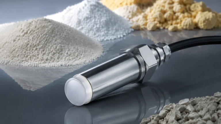
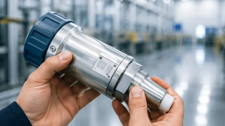
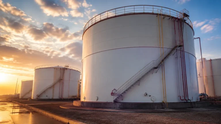
In the landscape of industrial automation and process control, the accurate measurement of liquids and solids within tanks, silos, and open channels is fundamental. A "sensor de nivel," or level sensor, serves as the primary interface between physical storage and digital monitoring systems. These devices are essential for ensuring operational safety, optimizing inventory management, and maintaining the consistency of chemical processes.
For engineers and procurement specialists, selecting the appropriate technology requires a deep understanding of the physical principles governing measurement, the environmental constraints of the application, and the specific characteristics of the media being measured. This guide provides a comprehensive technical overview of modern level measurement technologies, selection criteria, and practical installation strategies for industrial environments.
1. Core Measurement Principles
Before selecting a sensor de nivel, it is necessary to understand the underlying physics that allow these instruments to detect the surface of a material. Industrial level sensors generally fall into two categories: continuous measurement and point level detection.
Radar Level Measurement (Time of Flight)
Radar sensors utilize electromagnetic waves, typically in the microwave frequency range (6 GHz to 80 GHz). There are two primary types:
* Non-contact Radar: The sensor emits a signal that reflects off the surface of the medium and returns to the antenna. The distance is calculated based on the time it takes for the signal to travel (Time of Flight) or the frequency shift (FMCW – Frequency Modulated Continuous Wave).
* Guided Wave Radar (GWR): The microwave pulse travels along a physical probe (rod or cable). This technology is highly effective for low-dielectric liquids and applications with turbulence or foam, as the probe concentrates the energy and reduces signal loss.
Ultrasonic Level Measurement
Ultrasonic sensors function similarly to radar but use acoustic waves instead of electromagnetic pulses. The transducer emits an ultrasonic pulse that bounces off the material surface. The time elapsed between emission and reception is proportional to the distance. Because sound speed is affected by air temperature, these sensors typically include integrated temperature compensation to maintain accuracy.
Hydrostatic Level Measurement
This principle relies on the relationship between the height of a liquid column and the pressure exerted at the base. The formula $P = \rho \cdot g \cdot h$ (where $P$ is pressure, $\rho$ is density, $g$ is gravity, and $h$ is height) allows the sensor to calculate the level based on the weight of the liquid. These sensors are often submersible or mounted to the bottom of a vessel via a flange.
Magnetic Level Gauges and Switches
Magnetic sensors utilize a float containing an internal magnet. As the liquid level changes, the float moves along a chamber or tube. In a magnetic level gauge, this movement flips external magnetic flags for visual indication. In a transmitter setup, the magnet interacts with reed switches or a magnetostrictive wire to provide a continuous electronic signal.
2. Technical Selection Criteria
Choosing the right sensor de nivel is not a "one-size-fits-all" process. Engineers must evaluate several variables to ensure long-term reliability and accuracy.
Media Characteristics
* Dielectric Constant ($ε_r$): For radar sensors, the reflectivity of the surface depends on the dielectric constant. Materials with low $ε_r$ (like oils or hydrocarbons) reflect less energy than water-based liquids.
* Viscosity and Coating: High-viscosity liquids can coat probes or clog pressure diaphragms. In these cases, non-contact radar or flush-diaphragm hydrostatic transmitters are preferred.
* Corrosivity: The chemical compatibility of the wetted parts (e.g., SS316L, PTFE, PVDF) must be verified against the stored medium.
Process Conditions
* Temperature and Pressure: Extreme temperatures (above 200°C) or high pressures (above 40 bar) may rule out ultrasonic sensors due to changes in sound propagation, making high-frequency radar or specialized magnetic gauges more suitable.
* Turbulence and Foam: Heavy foam can absorb ultrasonic and radar signals. Guided wave radar is often the most robust solution for agitated or foaming surfaces.
Tank Geometry
Internal obstructions such as agitators, heating coils, or ladders can create false echoes for non-contact sensors. Understanding the "beam angle" of a sensor is critical to ensure the signal path remains clear.
3. Technology Comparison Table
The following table compares the most common technologies used in industrial level measurement to assist in the initial screening process.
| Technology | Accuracy | Range | Typical Applications | Limitations |
| :— | :— | :— | :— | :— |
| Non-contact Radar | ±2 mm | Up to 100 m | Acids, alkalis, oils, solids | High cost; sensitive to heavy foam |
| Guided Wave Radar | ±2 mm | Up to 75 m | Low dielectric liquids, small tanks | Contacting; probe can be damaged by agitators |
| Ultrasonic | ±0.25% of range | Up to 30 m | Water treatment, open channels | Sensitive to dust, steam, and vacuum |
| Hydrostatic | ±0.1% to 0.5% | Up to 200 m | Deep wells, vented tanks | Requires constant density; sensitive to pressure changes |
| Magnetic Gauge | ±5 mm to 10 mm | Up to 6 m | Boilers, oil/water separators | Contacting; moving parts require maintenance |
For a detailed look at specific instrument specifications and to Review product options and application support, consulting the technical documentation on our Main Page is recommended.
4. Installation and Engineering Considerations
Correct installation is as important as selecting the right technology. Even the most advanced sensor de nivel will fail to provide accurate data if poorly positioned.
Nozzle and Mounting Position
For radar and ultrasonic sensors, the device should be mounted away from the tank wall to avoid interference from side-wall reflections. A general rule is to keep the sensor at least 200 mm from the wall for every 1 meter of tank height. Additionally, the sensor should not be installed directly above the material inlet, as the falling stream will cause erratic readings.
Dead Zones (Blocking Distance)
All top-mounted sensors have a "dead zone" or blocking distance near the transducer where measurement is impossible. For ultrasonic sensors, this can range from 200 mm to 800 mm depending on the frequency. Engineers must ensure the maximum fill level of the tank does not enter this zone.
Pressure Venting for Hydrostatic Sensors
When using a hydrostatic sensor de nivel in a sealed tank, the sensor must be able to compensate for the headspace pressure. This is usually achieved by using a differential pressure transmitter or a vented cable that allows the sensor to reference atmospheric pressure.
Alignment and Leveling
Non-contact sensors must be mounted perpendicular to the liquid surface. A slight tilt can cause the signal to reflect away from the receiver, resulting in a "loss of echo" error. Many modern radar units include swivelling flanges to simplify this alignment.

5. Limitations and Operational Risks
While modern sensors are highly sophisticated, they are not immune to environmental factors that can compromise data integrity.
1. Vapor and Condensation: In high-humidity environments, condensation can form on the face of an ultrasonic transducer, effectively "blinding" the sensor. Radar sensors with PTFE drip-off antennas are designed to mitigate this risk.
2. Density Fluctuations: Hydrostatic sensors measure weight, not volume. If the temperature of a liquid changes significantly, its density changes, which will lead to a linear error in level calculation unless a temperature-compensated system is used.
3. Vacuum Conditions: Ultrasonic waves cannot travel through a vacuum. In vacuum-distillation columns, radar (which uses electromagnetic waves) is the only viable non-contact option.
4. Dust and Solids: In silos containing powders or grains, dust clouds can attenuate ultrasonic signals. High-frequency radar (80 GHz) is typically required to penetrate dust and provide a reliable return from the uneven surface of solids.
6. Frequently Asked Questions (FAQ)
Q: Can a sensor de nivel be used for both liquids and solids?
A: Some technologies, like radar, are versatile enough for both. However, the antenna design and software algorithms for solids measurement are different because solids do not form a flat, horizontal surface like liquids.
Q: What is the difference between a level transmitter and a level switch?
A: A level transmitter provides continuous measurement (e.g., 4-20mA or Modbus signal) showing exactly how much material is in the tank. A level switch is a point-level device that only triggers an alert when the material reaches a specific high or low threshold.
Q: How often do these sensors require calibration?
A: This depends on the technology. Hydrostatic sensors may drift over time and require annual calibration. Radar and ultrasonic sensors are generally more stable but should be verified periodically against a manual sounding tape.
Q: Is guided wave radar better than non-contact radar?
A: Not necessarily. Guided wave radar is better for low-dielectric fluids and turbulent surfaces, but non-contact radar is preferred for corrosive media or applications where you want to avoid sticking a probe into the material.
Conclusion
Selecting a sensor de nivel involves a systematic evaluation of the physical environment and the chemical properties of the process media. By understanding the measurement principles of radar, ultrasonic, and hydrostatic technologies, and by adhering to strict installation guidelines, industrial facilities can ensure high levels of accuracy and safety. For further technical assistance or to explore our full range of industrial measurement solutions, please visit our Main Page for comprehensive product specifications and engineering support.