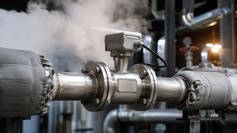
Ion Transmitter
Ion Transmitter
In the landscape of industrial process control and water quality management, the ion transmitter serves as a critical bridge between raw electrochemical data and actionable process intelligence. While level measurement instruments—such as those found on the Main Page of leading manufacturers—ensure the quantity of a liquid is monitored, ion transmitters provide the necessary insight into the chemical composition and quality of that liquid. This guide explores the technical principles, selection criteria, and practical application of ion transmitters in B2B industrial environments.
Understanding the Role of Ion Transmitters in Industrial Processes
An ion transmitter is an electronic device designed to convert the low-impedance, millivolt signal generated by an ion-selective electrode (ISE) into a standardized industrial output, such as 4-20mA, RS485 Modbus, or HART protocol. These devices are essential in sectors where the concentration of specific ions directly impacts product quality, environmental compliance, or equipment longevity.
In industries ranging from semiconductor manufacturing to municipal wastewater treatment, monitoring ions like fluoride, chloride, nitrate, or calcium is a daily necessity. The transmitter does not merely relay a signal; it performs complex calculations, including temperature compensation and linearization, to ensure that the data provided to a PLC (Programmable Logic Controller) or SCADA system is accurate and reliable.
Measurement Principles: The Science Behind Ion-Selective Electrodes
The operation of an ion transmitter is rooted in potentiometry. The primary sensing element is the Ion-Selective Electrode (ISE).
The Nernst Equation
At the heart of ion measurement is the Nernst Equation, which describes the relationship between the electrical potential of an electrode and the activity of the ions in the solution. The equation is generally expressed as:
E = E0 + (2.303 RT / nF) log(a)
Where:
* E is the total potential (measured in mV).
* E0 is the standard hydrogen electrode potential.
* R is the universal gas constant.
* T is the absolute temperature in Kelvin.
* n is the charge of the ion.
* F is the Faraday constant.
* a is the activity of the ion.
Selective Permeability
An ISE features a specialized membrane—which may be glass, solid-state, or PVC-based—that allows only the target ion to interact with the internal electrode. When the probe is immersed, a potential difference is created across this membrane. The ion transmitter measures this potential against a stable reference electrode. Because the potential is logarithmic relative to concentration, the transmitter’s internal processor must linearize the signal to provide a reading in mg/L or ppm (parts per million).
Key Components of an Industrial Ion Measurement System
A complete ion monitoring loop consists of several integrated components, each playing a vital role in data integrity:
1. Ion-Selective Electrode (ISE): The primary sensor that reacts to the specific ion of interest.
2. Reference Electrode: Provides a stable, constant potential against which the ISE potential is measured. In many modern industrial designs, the ISE and reference are combined into a single "combination probe."
3. Temperature Sensor (Pt100/Pt1000): Since ion activity is highly temperature-dependent, real-time temperature data is required for the transmitter to apply compensation algorithms.
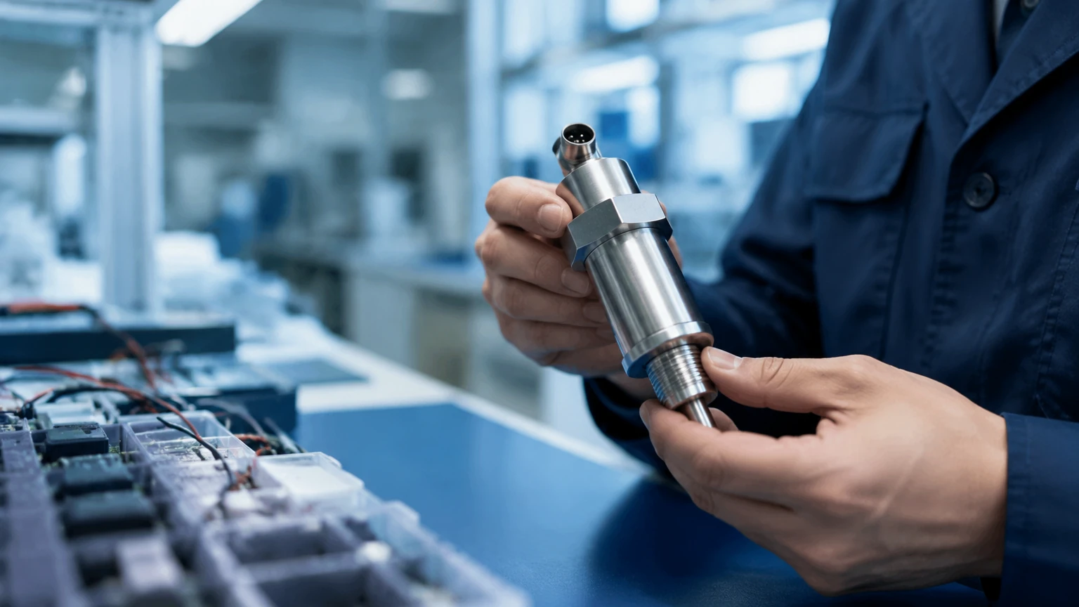
4. The Transmitter Unit: The "brain" of the system. It houses the display, signal processor, and output modules. It is typically rated IP65 or higher for industrial environments.
5. Cabling: High-impedance cables are required to prevent signal loss or interference between the probe and the transmitter.
Selection Criteria for Ion Transmitters
Choosing the right ion transmitter requires an evaluation of both the chemical environment and the integration requirements of the facility. Engineers should consider the following factors:
Ion Type and Range
Transmitters are often multi-parameter but require specific electrodes for different ions. Common industrial ions include:
| Target Ion | Typical Measurement Range | Primary Industry Applications |
| :— | :— | :— |
| Fluoride (F-) | 0.01 – 1,000 mg/L | Semiconductor, Drinking Water, Glass Etching |
| Chloride (Cl-) | 1 – 10,000 mg/L | Cooling Towers, Desalination, Food & Beverage |
| Nitrate (NO3-) | 0.1 – 500 mg/L | Wastewater Treatment, Agriculture, Hydroponics |
| Calcium (Ca2+) | 0.5 – 5,000 mg/L | Water Softening, Construction Materials |
| Potassium (K+) | 0.1 – 1,000 mg/L | Fertilizer Production, Power Plant Steam Loops |
Environmental Conditions
* Temperature: Ensure the transmitter and probe can handle the process temperature. Most standard probes operate between 0°C and 50°C (32°F to 122°F), though high-temperature versions exist.
* Pressure: For in-line installations, the probe must withstand the process pressure, often up to 6 bar (approx. 87 psi).
* Housing Material: For corrosive environments, plastic housings (ABS or PC) are preferred, while stainless steel is used for heavy-duty industrial settings.
Output and Communication
Modern B2B applications require seamless integration. Look for transmitters offering:
* Dual 4-20mA outputs (one for ion concentration, one for temperature).
* RS485 Modbus RTU for digital networking.
* Adjustable relay contacts for high/low alarms or dosing control.
Integration with Level Measurement Systems
In many industrial applications, such as chemical storage tanks or reaction vessels, ion concentration monitoring is performed in tandem with level measurement. For instance, in a wastewater neutralization tank, a radar level meter or ultrasonic sensor (available through the Main Page) ensures the tank does not overflow, while the ion transmitter monitors the concentration of contaminants to ensure they meet discharge limits.
Integrating these two data points allows for automated mass-balance calculations. If the level is rising but the ion concentration is falling, the system can infer that dilution is occurring. Conversely, if both rise, it indicates a high-concentration influx that may require immediate chemical treatment.
Installation Guidelines and Best Practices
Proper installation is the most significant factor in the longevity and accuracy of an ion transmitter system.
Probe Placement
* Immersion Depth: The probe must be fully submerged, but avoid placing it too close to the bottom of a tank where sediment can accumulate and coat the membrane.
* Flow Velocity: In-line sensors require a consistent flow to prevent the buildup of stagnant liquid, which can lead to sluggish response times. A flow rate between 0.1 m/s and 0.5 m/s is generally ideal.
* Orientation: Probes should typically be installed at an angle (at least 15° from horizontal) to prevent air bubbles from being trapped on the sensing membrane, which would cause erratic readings.
Wiring and Interference
Ion transmitters handle high-impedance signals that are susceptible to electromagnetic interference (EMI).
* Use shielded cables and ensure they are separated from high-voltage power lines.
* Ensure the transmitter is properly grounded to the process earth to eliminate ground loop noise.
Maintenance, Calibration, and Troubleshooting
Unlike level meters, which are often non-contact and low-maintenance, ion transmitters require regular attention due to the sacrificial nature of electrochemical probes.
Calibration Protocols
Calibration should be performed at least monthly, or more frequently in harsh environments. A two-point calibration is standard:
1. Low Standard: A solution with a known concentration at the lower end of the expected process range.
2. High Standard: A solution at the upper end of the range.
The transmitter calculates the "slope" of the electrode. A theoretical slope for a monovalent ion at 25°C is approximately 59.16 mV per decade of concentration. If the measured slope drops below 85% of the theoretical value, the electrode likely needs cleaning or replacement.
Cleaning Procedures
* Protein Buildup: Use an acidic pepsin solution.
* Grease and Oil: Use a mild detergent or isopropyl alcohol (check membrane compatibility first).
* Inorganic Scale: Use a 0.1M HCl solution.
Limitations and Interference Factors
While ion transmitters are powerful tools, they have inherent limitations that engineers must account for during the design phase:
1. Interference Ions: No membrane is perfectly selective. For example, a chloride electrode may also respond to bromide or iodide ions if they are present in the solution. This is known as the selectivity coefficient.
2. Ionic Strength: ISEs measure ion *activity*, not total concentration. In solutions with very high total dissolved solids (TDS), the relationship between activity and concentration changes. Adding an Ionic Strength Adjustor (ISA) buffer to a side-stream sample can mitigate this.
3. Lifespan: Industrial ion probes are consumables. Depending on the chemical aggressiveness of the process, a probe may last anywhere from 6 months to 2 years.
4. Minimum Detection Limits: Every ion transmitter system has a lower limit (often around 0.01 to 0.1 mg/L) below which the signal becomes indistinguishable from background noise.
Frequently Asked Questions (FAQ)
Q: Can one ion transmitter monitor multiple different ions simultaneously?
A: Most industrial transmitters are designed for a single or dual-channel input. While some high-end controllers can handle multiple probes, each specific ion requires its own dedicated electrode and usually its own dedicated input channel on the transmitter for proper calibration.
Q: How far can the transmitter be located from the probe?
A: Without a pre-amplifier, the distance should typically be kept under 10 meters (33 feet) due to the high-impedance signal. If longer distances are required, a transmitter with a built-in pre-amplifier or a digital sensor (Modbus-direct) should be used.
Q: Why does my reading drift even after calibration?
A: Drift is often caused by temperature fluctuations that exceed the compensation range, or by the reference electrode junction becoming clogged. Check the "junction" of the probe for discoloration or salt buildup.
Q: Is an ion transmitter the same as a conductivity meter?
A: No. A conductivity meter measures the total ability of a solution to conduct electricity (all ions combined), whereas an ion transmitter uses a selective membrane to isolate and measure the concentration of one specific type of ion.
By understanding these technical nuances, process engineers can successfully deploy ion transmitters to maintain rigorous quality standards. For more information on integrating chemical analysis with physical level monitoring, users are encouraged to review the comprehensive instrumentation options available on the Welk Main Page.