Steam Flow Meters
Steam Flow Meters
Steam remains one of the most critical energy carriers in modern industrial processes, used extensively for heating, power generation, and sterilization. However, steam is also one of the most challenging fluids to measure accurately due to its high temperature, high pressure, and varying states (saturated versus superheated). Implementing robust steam flow meters is essential for energy balancing, cost allocation, and process optimization. This guide examines the primary measurement technologies, selection criteria, and installation best practices for steam applications.
Understanding Steam Flow Measurement Principles
Before selecting a meter, it is necessary to understand the physical principles that govern flow measurement in steam systems. Unlike liquids, steam is a compressible gas, meaning its density changes significantly with variations in pressure and temperature. Consequently, most industrial applications require mass flow measurement or volumetric measurement with integrated compensation.
Vortex Shedding Principle
Vortex flow meters are among the most common choices for steam. They operate on the Karman Vortex Street principle. When steam flows past a non-streamlined object (a bluff body) placed in the pipe, it creates alternating vortices. The frequency at which these vortices are shed is directly proportional to the velocity of the steam.
Because the shedding frequency is independent of fluid density, vortex meters provide an accurate volumetric flow rate. To obtain mass flow, these meters often include an integral temperature sensor and sometimes a pressure sensor to calculate real-time density. They are favored for their lack of moving parts and high durability in high-velocity steam lines.
Differential Pressure (DP) Principle
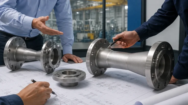
Differential pressure measurement is a traditional yet highly reliable method. It relies on Bernoulli’s principle, which states that as the speed of a moving fluid increases, the pressure within the fluid decreases. By placing a primary element—such as an orifice plate, Venturi tube, or Pitot tube—in the flow stream, a localized pressure drop is created.
Secondary transmitters measure the pressure difference across the element. The flow rate is proportional to the square root of the differential pressure. While versatile, DP systems require careful maintenance of impulse lines and often result in a permanent pressure loss within the system.
Turbine and Rotameter Principles
Turbine flow meters utilize a multi-bladed rotor suspended in the flow stream. The steam’s kinetic energy causes the rotor to spin at a speed proportional to the flow velocity. While highly accurate in clean, steady-state conditions, the mechanical bearings in turbine meters are susceptible to wear from the high temperatures and potential water hammer associated with steam.
Variable area meters (rotameters) use a float in a tapered tube. As flow increases, the float rises until the upward force of the steam balances the weight of the float. These are typically used for local indication in smaller lines where high precision is less critical than cost and simplicity.
Saturated vs. Superheated Steam Considerations
The state of the steam dictates the complexity of the measurement system.
1. Saturated Steam: This exists at a specific temperature for a given pressure. If the pressure is known, the temperature (and density) is fixed. Therefore, a vortex meter with only temperature compensation can often calculate mass flow accurately.
2. Superheated Steam: This steam has been heated beyond its saturation point. Temperature and pressure are independent variables. To measure superheated steam accurately, a multivariable approach is required, measuring both pressure and temperature simultaneously to determine the actual density from steam tables.
Technical Selection Table
Choosing the right technology requires balancing accuracy requirements against installation constraints and budget. The following table provides a comparison of common steam flow meters.
| Technology | Typical Accuracy | Turndown Ratio | Pressure Drop | Best Application |
| :— | :— | :— | :— | :— |
| Vortex Shedding | ±1.0% of rate | 10:1 to 20:1 | Medium | General plant steam, high velocity |
| Orifice Plate (DP) | ±2.0% to 3.0% | 4:1 | High | Constant flow, legacy systems |
| Venturi Tube (DP) | ±0.5% to 1.5% | 4:1 | Low | High-pressure main lines |
| Spring-Loaded VA | ±2.0% | 10:1 | Medium | Small pipes, fluctuating loads |
| Turbine Meter | ±0.5% to 1.0% | 10:1 to 25:1 | Medium | Clean, dry superheated steam |
Installation Considerations and Best Practices
Even the most advanced steam flow meters will fail to provide accurate data if installed incorrectly. Steam systems are inherently harsh, and installation must account for thermal expansion and condensate management.
Straight Pipe Runs
Most flow meters require a fully developed flow profile to measure accurately. Turbulence caused by elbows, valves, or reducers can introduce significant errors. A general rule of thumb is to provide at least 10 to 20 nominal diameters (D) of straight pipe upstream and 5D downstream of the meter. If space is limited, flow straighteners or conditioners may be necessary.
Condensate Management
Steam lines inevitably contain some liquid water (condensate), especially during startup. If condensate hits the sensor at high speeds (water hammer), it can destroy the bluff body of a vortex meter or the blades of a turbine.
* Steam Traps: Ensure a high-capacity steam trap is installed upstream of the meter to remove moisture.
* Y-Strainers: Install strainers to protect against pipe scale and debris.
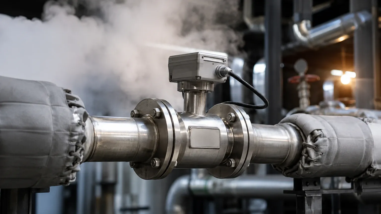
* Orientation: For horizontal pipes, the meter electronics should often be mounted to the side (at the 3 o'clock or 9 o'clock position) to prevent the electronics from being overheated by rising heat or submerged by bottom-dwelling condensate.
Insulation
Insulating the flow meter body and the adjacent piping is critical. This prevents excessive heat loss, which would lead to increased condensate formation and potential measurement inaccuracies. However, ensure that the transmitter electronics are left uninsulated to allow for ambient cooling.
Limitations and Common Risks
Engineering teams must be aware of the following limitations when deploying steam flow meters:
* Turndown Limits: Every meter has a minimum flow velocity (the "cutoff") below which it cannot measure. If a process has highly variable seasonal loads, a single meter may not be able to capture low-flow conditions accurately.
* Pressure Drop: Orifice plates create a permanent loss of energy. Over years of operation, the cost of the energy required to overcome this pressure drop can exceed the initial cost of a more expensive, low-pressure-drop meter like a Venturi or Vortex.
* Calibration Drift: In DP systems, the sharp edges of an orifice plate can erode over time due to high-velocity steam, leading to a consistent under-measurement of flow.
Integration with Level Measurement Systems
In many industrial boiler applications, steam flow measurement is not an isolated requirement. It is often paired with level measurement to maintain the "mass balance" of the boiler. For instance, in a drum level control system, the feed-water input must match the steam output.
Engineers often utilize data from the Main Page to select complementary level sensors, such as guided wave radar or magnetic level gauges, to work alongside steam flow meters. This holistic approach ensures that as steam demand fluctuates, the boiler water level remains within safe operating limits, preventing dry-firing or carryover of water into the steam lines.
Frequently Asked Questions (FAQs)
Q: Can I use an ultrasonic flow meter for steam?
A: While ultrasonic meters are common for liquids and gases, steam presents challenges due to high temperatures and the noise generated by steam flow. High-end transit-time ultrasonic meters designed specifically for steam are available but are generally more expensive than vortex meters.
Q: Why is my vortex meter reading zero even when I know steam is flowing?
A: This is often due to the flow rate being below the meter's "low-flow cutoff." Vortex meters require a minimum Reynolds number to shed vortices. If the steam velocity is too low, no vortices are formed, and the meter will report zero.
Q: How often should steam flow meters be calibrated?
A: For billing or high-accuracy process control, annual calibration is recommended. For general monitoring, a check every two years may suffice, provided the steam quality is high and there are no signs of physical wear on the primary elements.
Q: Should I measure volumetric flow or mass flow?
A: Because steam is compressible, volumetric flow (e.g., m³/h) is rarely useful on its own. Mass flow (e.g., kg/h) provides a true representation of the energy being delivered and is the standard for industrial B2B applications.
Conclusion
Selecting the appropriate steam flow meter requires a deep understanding of the specific process conditions, including the steam state, expected flow ranges, and physical piping constraints. Vortex meters offer a robust, versatile solution for most general industrial needs, while differential pressure systems remain a staple for high-pressure main lines. By adhering to strict installation guidelines and considering the integration with level measurement systems, plant operators can achieve the precision necessary for efficient energy management. For more information on industrial measurement solutions and technical specifications, please refer to the Main Page.