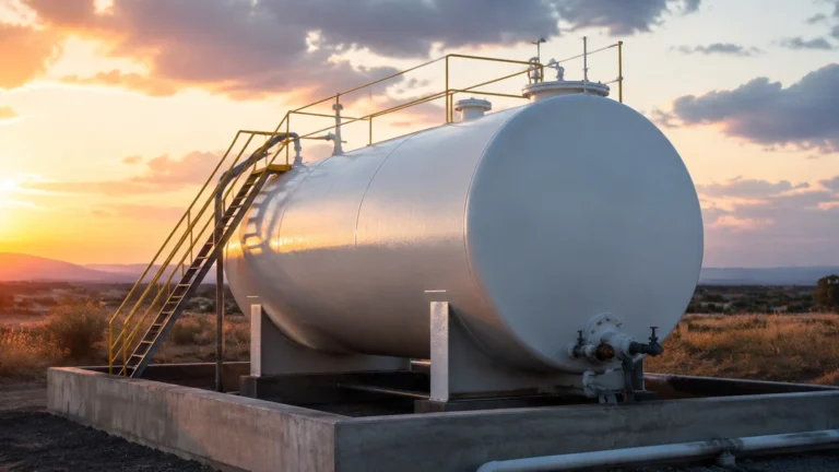
L 51
L 51
In the landscape of industrial process control, the L 51 series stands as a critical instrument for hydrostatic level measurement. Designed to provide continuous monitoring of liquid levels in a variety of environments—ranging from deep groundwater wells to industrial chemical tanks—the L 51 utilizes the relationship between liquid height and static pressure. This article serves as a comprehensive engineering reference for the L 51, detailing its measurement principles, technical specifications, selection criteria, and installation best practices to ensure long-term reliability in the field.
For engineers and procurement professionals seeking a broader overview of level measurement technologies, visiting the Main Page of industrial instrumentation providers can provide additional context on how hydrostatic solutions compare with radar or ultrasonic alternatives.
The Measurement Principle of the L 51
The L 51 operates on the hydrostatic pressure principle. This method is based on the physical law that the pressure at a specific point within a static liquid is proportional to the weight of the liquid column above that point. This relationship is mathematically expressed as:
P = ρ × g × h
Where:
- P is the hydrostatic pressure (measured at the sensor diaphragm).
- ρ (rho) is the density of the liquid.
- g is the local acceleration due to gravity (approximately 9.81 m/s²).
- h is the height of the liquid column (the level being measured).
In an L 51 transmitter, a high-precision pressure sensing element (typically piezoresistive silicon or ceramic) is housed within a stainless steel probe. This probe is submerged into the liquid. The sensor detects the total pressure exerted by the liquid. To ensure accuracy, the L 51 must account for atmospheric pressure acting on the surface of the liquid. This is achieved through a vented cable that contains a small capillary tube, allowing the back of the sensor diaphragm to remain at atmospheric pressure. The resulting measurement is "gauge pressure," which directly correlates to the height of the liquid regardless of changes in local barometric pressure.
Technical Architecture and Key Features
The L 51 is engineered for durability in submerged conditions. Unlike top-mounted sensors that may struggle with foam or internal tank obstructions, the L 51 is positioned at the bottom of the vessel or well, making it immune to many surface-level disturbances.
1. Sensor Construction
The probe body of the L 51 is usually constructed from 304 or 316L stainless steel, providing excellent resistance to corrosion in water and mild chemical applications. For more aggressive media, specialized coatings or alternative materials like Tantalum or Hastelloy may be employed for the diaphragm.
2. Signal Conditioning and Output
The internal electronics convert the mechanical pressure into a standardized industrial signal. The most common output is a 2-wire 4-20mA analog signal, which is highly resistant to electrical noise over long cable runs. Digital options, such as RS485 Modbus or HART protocols, are also available for integration into complex SCADA systems or IoT platforms.
3. Ingress Protection
Given its submerged nature, the L 51 features an IP68 rating. The cable entry is hermetically sealed to prevent moisture from entering the electronics, which is a common failure point in lower-quality hydrostatic sensors.
L 51 Selection Criteria
Choosing the correct L 51 configuration requires a detailed understanding of the application environment. The following table provides a reference for matching specifications to process needs:
| Parameter | Standard Water Application | Chemical / Aggressive Media | Deep Well / Borehole |
| :— | :— | :— | :— |
| Housing Material | SS304 or SS316L | SS316L with PTFE Coating | SS316L |
| Cable Material | PVC or PE | PTFE or FEP | Reinforced PUR |
| Accuracy Class | 0.5% FS | 0.25% FS | 0.25% or 0.1% FS |
| Pressure Range | 0–10m H2O | 0–5m H2O | 0–200m H2O |
| Output Signal | 4-20mA | 4-20mA / HART | RS485 Modbus |
| Protection | Lightning Protection (Optional) | Chemical Resistance | High Tensile Strength Cable |
Critical Considerations for Selection
- Liquid Density: Since the L 51 measures pressure, any change in the liquid's specific gravity will affect the level reading. If the density is variable (e.g., in a mixing tank), a differential pressure approach or frequent recalibration may be necessary.
- Temperature Range: Standard L 51 units operate between -20°C and +80°C. For high-temperature industrial processes, specialized cooling segments or remote seals are required.
- Cable Length: The cable length must exceed the maximum depth of the tank or well. It is also vital to account for the distance from the top of the vessel to the junction box.
Installation Guidelines for the L 51
Proper installation is paramount to the longevity and accuracy of the L 51. Mechanical stress or improper electrical connections are the leading causes of sensor drift and failure.
Mechanical Installation
1. Positioning: The sensor should be placed as close to the bottom of the tank as possible, but not resting in silt or sludge. If the bottom of the tank contains sediment, suspend the L 51 approximately 100mm to 200mm above the base.
2. Stilling Wells: In tanks with high turbulence or agitators, the L 51 should be installed inside a stilling well (a perforated pipe). This protects the sensor from lateral forces and prevents the cable from tangling.
3. Cable Support: For deep installations, the weight of the cable can strain the internal connections. Use a cable clamp or specialized hanger at the point of exit from the well or tank to take the load off the electrical terminals.
Electrical and Atmospheric Connection
1. Venting: The capillary tube inside the cable must remain unobstructed. If the cable terminates in a junction box, ensure the box is vented but protected from water ingress (using a breathable GORE-TEX vent or a desiccant cartridge).
2. Grounding: To prevent damage from electrical surges or lightning, the shield of the L 51 cable should be grounded at the control cabinet side. In outdoor or deep well applications, secondary surge protection devices are highly recommended.

Limitations and Operational Risks
While the L 51 is a versatile tool, it is not a "one-size-fits-all" solution. Engineers should be aware of the following limitations:
- Pressurized Vessels: A standard L 51 cannot be used in a sealed, pressurized tank because it cannot distinguish between the pressure exerted by the liquid and the pressure of the gas blanket above it. In such cases, a differential pressure transmitter is required.
- Viscous and Clogging Liquids: Liquids with high solids content or those that tend to crystallize can block the pressure port of the L 51, leading to false readings. Open-diaphragm versions are better suited for these "dirty" applications.
- Specific Gravity Shifts: As mentioned, the sensor is calibrated to a specific density. If a tank is used for different liquids at different times, the output will need to be scaled accordingly in the PLC or display unit.
Maintenance and Troubleshooting
The L 51 is largely maintenance-free due to its lack of moving parts. However, periodic checks are recommended:
- Inspection for Bio-fouling: In wastewater or open water applications, algae or barnacles can grow on the sensor. Clean the diaphragm gently with a soft cloth and mild detergent; never use sharp objects to clear the pressure port.
- Desiccant Check: If a desiccant cartridge is used in the junction box to protect the vent tube, check its color. If it has turned from blue to pink (or clear), it must be replaced to prevent moisture from migrating down the tube into the sensor.
Common Troubleshooting Steps
- Fixed Output (e.g., 4mA or 20mA): Check for cable breaks or a short circuit. Ensure the power supply is within the specified range (usually 12-36V DC).
- Erratic Readings: Often caused by moisture in the vent tube or electrical interference. Check the integrity of the vent tube and ensure the cable is not run alongside high-voltage power lines.
- Zero Drift: Small shifts in the zero point can occur over years of service. Most L 51 units can be recalibrated at the transmitter or adjusted within the control system software.
Frequently Asked Questions (FAQ)
Q: Can the L 51 cable be shortened in the field?
A: Yes, the cable can be cut to length. However, extreme care must be taken not to block or crimp the internal vent tube. The use of a specialized junction box designed for hydrostatic transmitters is recommended to maintain the atmospheric reference.
Q: Is the L 51 suitable for drinking water?
A: Yes, provided the materials (SS316L and the cable jacket) are food-grade or certified for potable water use. PE (Polyethylene) cables are often preferred for drinking water applications.
Q: How does the L 51 handle lightning strikes in deep wells?
A: Many L 51 units include internal surge protection. However, for maximum safety in lightning-prone areas, an external surge protector should be installed at the wellhead and the cable shield must be properly grounded.
Conclusion
The L 51 is a robust and cost-effective solution for many liquid level challenges. By understanding the hydrostatic principle and ensuring proper installation and material compatibility, users can achieve high-precision measurements with minimal maintenance. For further technical data, mounting accessories, or to explore other level measurement technologies like radar or ultrasonic sensors, please refer to the Main Page for a full catalog of industrial solutions. Confirmation of liquid density, tank pressure, and chemical compatibility remains the most important step before finalizing any L 51 implementation.