Lift Station for Sewer
Lift Station for Sewer
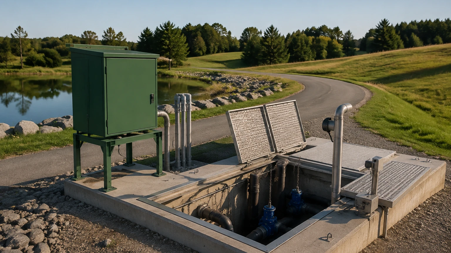
In municipal and industrial wastewater management, the lift station for sewer serves as a critical junction. Because gravity-fed sewer lines must maintain a specific downward slope to ensure flow, they eventually reach depths where further excavation becomes impractical or cost-prohibitive. At these points, a lift station—also known as a pumping station—is employed to elevate the wastewater to a higher elevation or to a treatment facility.
Reliable operation of these stations depends heavily on precise level measurement. Inaccurate data can lead to pump dry-running, basin overflows, or unnecessary energy consumption. This guide examines the engineering principles, sensor selection, and installation requirements for monitoring levels within a lift station for sewer.
Understanding Level Measurement Principles
Before selecting an instrument for a lift station, it is essential to understand how different technologies interact with the volatile and often turbulent environment of a sewage wet well. Most modern systems utilize one of four primary measurement principles.
1. Ultrasonic (Non-Contact)
Ultrasonic sensors emit high-frequency sound pulses that bounce off the surface of the wastewater. The sensor measures the "Time-of-Flight" (ToF) for the echo to return. Since the speed of sound is known, the distance to the liquid is calculated, which is then converted into a level reading.
* Principle: Acoustic reflection.
* Suitability: Ideal for standard domestic sewage where foam is minimal.
2. Radar (Non-Contact)
Radar level meters, particularly those operating at 26 GHz or 80 GHz, use high-frequency electromagnetic waves. Unlike sound, these waves are unaffected by air temperature fluctuations, methane gas concentrations, or heavy steam.
* Principle: Microwave Time-of-Flight or Frequency Modulated Continuous Wave (FMCW).
* Suitability: Highly effective in deep wells or environments with heavy fumes and turbulence.
3. Hydrostatic (Contact)
Hydrostatic level transmitters are submersible pressure sensors. They are lowered to the bottom of the lift station and measure the pressure exerted by the liquid column above them. This pressure is directly proportional to the height of the liquid based on its density.
* Principle: Piezoresistive or ceramic pressure sensing.
* Suitability: Excellent for deep wells where surface foam or floating debris might interfere with non-contact sensors.
4. Point Level Switches (Contact)
Float switches or conductive probes provide discrete signals at specific heights. In a lift station for sewer, these are typically used as secondary safety backups to trigger high-level alarms or to provide a hard-wired "pump off" signal if the primary continuous sensor fails.
Technology Selection Criteria
Choosing the right instrument requires an analysis of the specific wastewater characteristics and the physical layout of the wet well. Engineers should consult the Main Page of technical documentation to compare specific model tolerances against site conditions.
| Feature | Ultrasonic Sensors | Radar Level Meters | Hydrostatic Transmitters |
| :— | :— | :— | :— |
| Measurement Range | Up to 15m (typically) | Up to 30m+ | Up to 100m |
| Accuracy | ±0.25% of range | ±2mm to ±5mm | ±0.1% to ±0.5% |
| Effect of Foam | High (absorbs signal) | Moderate (can penetrate) | None |
| Effect of Fumes/Gas | High (changes sound speed) | None | None |
| Maintenance | Low (non-contact) | Lowest (non-contact) | Moderate (cleaning required) |
| Cost | Economical | Premium | Moderate |
Engineering a Lift Station for Sewer
A lift station for sewer is more than just a pit with a pump; it is a sequenced system. The level instrument provides the data used by the Pump Station Controller or PLC to manage cycles.
Pump Sequencing
1. Stop Level: The lowest point at which pumps are deactivated to prevent cavitation and air intake.
2. Lead Pump Start: The level at which the first pump begins operation.
3. Lag Pump Start: If the lead pump cannot keep up with the inflow and the level continues to rise, the second pump is activated.
4. High-Level Alarm: A critical threshold indicating a potential overflow or pump failure.
Handling Turbulence and Solids
Sewage lift stations are high-energy environments. Inflow pipes often create significant surface turbulence and splashing. If using non-contact sensors like ultrasonic or radar, the beam must be positioned away from the inflow path to avoid "noise" in the data. For hydrostatic sensors, a stilling well (a perforated pipe) is often used to protect the sensor from the physical force of moving water and to prevent it from being swept into the pump intake.
Installation Considerations and Best Practices
Proper installation is as important as sensor selection. Even the most advanced radar level meter will fail if it is improperly positioned within the lift station for sewer.
Positioning and Mounting
* Dead Zones: Every non-contact sensor has a "blocking distance" or dead zone (typically 0.25m to 0.5m). The sensor must be mounted high enough that the maximum possible liquid level never enters this zone.
* Beam Angle: Non-contact sensors emit signals in a cone. Ensure there are no obstructions—such as ladders, pipes, or pump cables—within this cone, as they will cause false echoes.
* Vertical Alignment: The sensor face must be perfectly parallel to the liquid surface. A tilt of even a few degrees can significantly reduce signal strength.
Environmental Protection
Sewer environments are corrosive due to the presence of Hydrogen Sulfide (H2S) gas.
* Material Choice: Use PVDF or PTFE-coated sensors for non-contact applications. For hydrostatic sensors, ensure the cable jacket is made of high-density polyethylene (HDPE) or polyurethane (PUR) to resist chemical degradation.
* Lightning Protection: Since lift stations are often in isolated areas and connected to long cable runs, integrated surge protection is a mandatory requirement for the electronics.
Cabling and Venting
Hydrostatic sensors require a vented cable to compensate for changes in atmospheric pressure. This vent tube must remain unobstructed and be terminated in a dry junction box with a desiccant cartridge to prevent moisture from migrating down into the sensor internals.
Limitations and Operational Challenges
While modern instrumentation is robust, a lift station for sewer presents unique challenges that can limit performance.
* Grease and Fat Accumulation: In many municipal systems, "FOG" (Fats, Oils, and Grease) accumulates on the surface. This can coat hydrostatic sensors or create a thick crust that dampens ultrasonic signals. Regular cleaning or the use of flush-diaphragm sensors is necessary.
* Methane and H2S Concentrations: In deep wells, gas buildup can change the density of the air. This significantly affects ultrasonic accuracy because sound travels at different speeds through different gases. In these specific cases, radar or hydrostatic sensors are technically superior.
* Signal Multipath: In narrow concrete wet wells, radar signals may bounce off the walls before hitting the water. Using high-frequency 80 GHz radar with a narrow beam angle (e.g., 3° to 6°) helps eliminate these parasitic reflections.
Maintenance and Troubleshooting FAQ
Q: How often should level sensors in a lift station be calibrated?
A: For most digital sensors, annual verification is sufficient. However, hydrostatic sensors in heavy sludge applications should be pulled and cleaned every 3 to 6 months to prevent buildup on the sensing diaphragm.
Q: Why is my ultrasonic sensor giving erratic readings during heavy rain?
A: Heavy rain increases inflow, which often leads to increased turbulence and foam. Additionally, high humidity or condensation on the sensor face can interfere with the acoustic pulse. If this is a recurring issue, upgrading to a radar level meter is recommended.
Q: Can I use a standard pressure transmitter for a sewer lift station?
A: No. Standard transmitters are not designed for submersion or the corrosive nature of wastewater. You must use a specialized hydrostatic level transmitter with a large, non-clogging diaphragm and a chemical-resistant cable.
Q: What is the best way to prevent "ghost" echoes in a small wet well?
A: Utilize the "false echo suppression" or "mapping" feature in the sensor's software. This allows the instrument to recognize and ignore static reflections from internal structures like pipes or ladders.
Conclusion
Managing a lift station for sewer requires a balance of robust mechanical engineering and precise electronic monitoring. By understanding the measurement principles of ultrasonic, radar, and hydrostatic technologies, engineers can select the most cost-effective and reliable solution for their specific site conditions. Whether the priority is low maintenance through non-contact radar or high-accuracy depth measurement via hydrostatic pressure, the goal remains the same: ensuring the continuous, safe, and efficient movement of wastewater through the municipal network. For detailed specifications on industrial-grade level instruments, operators should Review product options and application support to ensure their infrastructure meets modern performance standards.