Level Monitoring
Level Monitoring
In industrial process control, level monitoring is the critical practice of measuring the height or volume of liquids, solids, or slurries within a vessel or container. Accurate level data is essential for inventory management, process safety, and operational efficiency. Whether managing a water treatment plant, a chemical reactor, or a fuel storage farm, selecting the appropriate technology requires a deep understanding of physics, media properties, and environmental constraints.
Effective level monitoring systems prevent overflows that could lead to environmental hazards or equipment damage, while also ensuring that pumps do not run dry. As automation becomes more sophisticated, the demand for high-precision, digital level measurement has grown, leading to a diverse range of sensors tailored to specific industrial challenges.
Principles of Level Measurement Technologies
Before selecting a device, engineers must understand the physical principles that govern different measurement methods. Level sensors are generally categorized into non-contact and contact-based technologies.
Radar Level Measurement (Non-contact and Guided Wave)
Radar technology utilizes electromagnetic waves to determine the distance to a product surface. There are two primary types: Frequency Modulated Continuous Wave (FMCW) and Pulsed Radar.
In non-contact radar, the sensor emits a high-frequency signal (typically 26 GHz or 80 GHz) toward the media. The signal reflects off the surface and returns to the antenna. The time-of-flight (ToF) or frequency shift is used to calculate the distance. High-frequency 80 GHz radar is particularly effective for level monitoring because it offers a narrow beam angle, allowing it to avoid internal tank obstructions like agitators or heating coils.
Guided Wave Radar (GWR) operates on the principle of Time Domain Reflectometry (TDR). Instead of broadcasting through the air, the microwave pulse travels along a metal probe or cable. This method is highly efficient for media with low dielectric constants or in applications where heavy foam and steam are present, as the probe guides the signal directly to the surface.
Ultrasonic Level Sensing
Ultrasonic sensors function by emitting high-frequency sound waves (above the range of human hearing). The sensor measures the time it takes for the sound pulse to travel to the surface and echo back. Because the speed of sound is affected by air temperature, these sensors usually include an integrated temperature probe to provide compensation for accurate calculations.
Ultrasonic level monitoring is a cost-effective solution for open-channel flow and liquid storage in atmospheric tanks. However, because it relies on a mechanical wave (sound), its performance can be degraded by heavy dust, surface foam, or vacuum conditions where there is no medium to carry the sound.
Hydrostatic Pressure Measurement
Hydrostatic level transmitters measure the pressure exerted by a liquid column at a specific point. The principle is based on the formula: $P = \rho \cdot g \cdot h$, where $P$ is pressure, $\rho$ (rho) is the density of the liquid, $g$ is gravity, and $h$ is the height of the liquid.
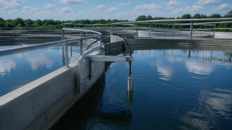
This method is widely used in water wells, reservoirs, and vented tanks. It is a contact-based method where the sensor (often a submersible probe or a flange-mounted diaphragm) must be compatible with the chemical properties of the fluid. It is important to note that if the density of the liquid changes due to temperature fluctuations, the level reading will require compensation.
Magnetic Level Gauges and Switches
Magnetic level gauges provide a clear visual indication of the level outside the tank using a bypass chamber. Inside the chamber, a float containing a permanent magnet moves with the liquid level. This magnet flips colored flaps on a scale or actuates external reed switches. This technology is preferred for high-pressure or high-temperature applications where power is not available or where a mechanical backup to electronic sensors is required for safety.
Selection Criteria for Industrial Level Monitoring
Choosing the right instrument involves more than just matching a sensor to a tank size. Engineers must evaluate several variables to ensure long-term reliability.
1. Media Properties: Is the liquid corrosive, viscous, or prone to coating? For corrosive acids, non-contact radar or PTFE-lined ultrasonic sensors are ideal. For solids like grain or cement, high-frequency radar with a dust-resistant lens is necessary.
2. Process Conditions: Consider the operating temperature and pressure. Hydrostatic sensors have limits based on diaphragm material, while radar can handle extreme temperatures exceeding 400°C.
3. Tank Geometry: The presence of baffles, agitators, or narrow nozzles influences the choice. A narrow beam 80 GHz radar can "see" past obstacles that would confuse an ultrasonic sensor.
4. Accuracy Requirements: For custody transfer or high-value chemical dosing, high-accuracy radar (±1 mm) is often required. For simple sump pump control, a level switch or ultrasonic sensor may suffice.
Practical Selection Table
The following table provides a general comparison of common level monitoring technologies used in industrial settings.
| Technology | Accuracy | Media Type | Temp/Pressure Limits | Typical Application |
| :— | :— | :— | :— | :— |
| 80 GHz Radar | Excellent (±1mm) | Liquids/Solids | Very High | Chemical reactors, tall silos |
| Guided Wave Radar | High (±2mm) | Liquids/Slurry | High | Oil/water interface, foaming tanks |
| Ultrasonic | Moderate (±0.25%) | Liquids | Low/Moderate | Water treatment, open sumps |
| Hydrostatic | Good (±0.1-0.5%) | Liquids | Moderate | Deep wells, vented water tanks |
| Magnetic Gauge | Visual | Liquids | High | Boiler drums, fuel storage |
For a comprehensive look at specific hardware configurations and technical specifications, engineers should consult the Main Page of the manufacturer’s technical catalog.
Installation and Engineering Best Practices
Correct installation is as vital as selecting the right technology. Even the most advanced radar sensor will fail if installed incorrectly.
* The Dead Zone (Blocking Distance): Every sensor has a "dead zone" near the antenna or probe where measurement is impossible. Ensure the maximum liquid level never enters this zone to avoid signal loss.
* Nozzle Design: For radar and ultrasonic sensors, the nozzle should be as short and wide as possible. If the nozzle is too long, the signal may reflect off the internal walls of the pipe before reaching the media.
* Avoiding the Center: In cylindrical tanks, avoid mounting the sensor in the exact center. This can cause "multiple echoes" where the signal bounces off the tank walls and converges back at the center, creating a false high-level reading.
* Vortex and Turbulence: If the tank has a high-speed agitator, the surface may become conical (vortex). In these cases, Guided Wave Radar or a stilling well for non-contact radar is recommended to provide a stable surface for measurement.
* Submersible Venting: For hydrostatic submersible sensors, the cable contains a small vent tube to compensate for atmospheric pressure. This tube must be kept clear of moisture and debris to prevent measurement drift.

Limitations and Operational Risks
While modern level monitoring systems are robust, they are not infallible. Understanding limitations helps in designing redundant systems.
* Dielectric Constant ($ε_r$): Radar relies on the reflectivity of the media. Materials with a very low dielectric constant (like certain oils or liquefied gases) reflect very little energy. In these scenarios, Guided Wave Radar or specialized high-sensitivity antennas are required.
* Foam and Vapor: Heavy, dense foam can absorb ultrasonic and radar signals. While 80 GHz radar can penetrate some light foam, thick protein-based foams often require contact-based measurement like hydrostatic or magnetic gauges.
* Build-up and Scaling: In wastewater or lime slurry applications, material can build up on the sensor face. Non-contact sensors are less prone to this, but even they can be blinded if a thick crust forms over the antenna. Self-cleaning functions or air purging systems may be necessary.
* Vacuum Conditions: Ultrasonic sensors cannot operate in a vacuum because sound requires a medium (air/gas) to travel. Radar is the standard choice for vacuum distillation columns.
Frequently Asked Questions (FAQs)
Q: How often should level monitoring sensors be calibrated?
A: This depends on the industry and the technology. Hydrostatic sensors may drift over time and usually require annual checks. Radar sensors are digital and inherently more stable, often only requiring a verification check every 2-3 years unless used in safety-critical (SIL) loops.
Q: Can one sensor measure both the level and the interface between two liquids?
A: Yes, Guided Wave Radar (GWR) is specifically designed for this. It can detect the top of a low-dielectric liquid (like oil) and the interface of a high-dielectric liquid (like water) beneath it simultaneously.
Q: What is the benefit of 80 GHz radar over 26 GHz radar?
A: The 80 GHz frequency allows for a much smaller antenna and a narrower beam (often down to 3 degrees). This makes it easier to install in small nozzles and allows it to avoid internal obstructions that would cause interference for a 26 GHz signal.
Q: Is hydrostatic measurement affected by tank pressure?
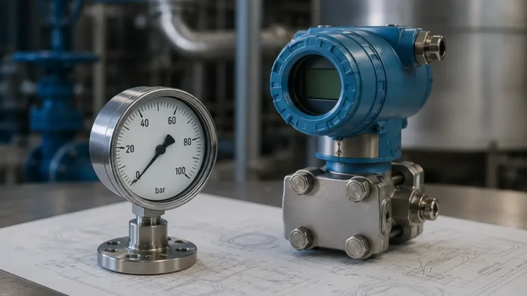
A: Yes. In a pressurized tank, a single hydrostatic sensor will measure both the liquid head and the gas pressure above it. To measure only the liquid level, a differential pressure (DP) transmitter must be used to subtract the top gas pressure from the total bottom pressure.
Conclusion
Level monitoring is a cornerstone of modern industrial automation. By understanding the measurement principles—from the electromagnetic reflections of radar to the pressure-based calculations of hydrostatic sensors—engineers can implement solutions that enhance safety and productivity. Successful implementation relies on a thorough analysis of the process media, vessel geometry, and environmental factors. For professionals seeking to optimize their processes, reviewing technical data and application-specific hardware on the Main Page is the recommended next step in the engineering design phase. Proper selection, combined with disciplined installation practices, ensures that level monitoring remains a reliable asset in any industrial facility.