Transmitter Liquid
Transmitter Liquid
In the landscape of industrial automation, the term "transmitter liquid" refers to the diverse array of instruments designed to measure and communicate the level of fluid media within tanks, vessels, and open channels. Selecting the appropriate transmitter for liquid applications is a fundamental task for process engineers, as the accuracy of these measurements directly impacts inventory management, process safety, and operational efficiency.
This guide explores the primary technologies used in liquid level measurement, their operating principles, and the technical criteria necessary for selecting the right instrument for specific industrial environments.
Core Principles of Liquid Level Measurement
Before selecting a transmitter, it is essential to understand the physical principles that govern different measurement technologies. Most industrial liquid level transmitters fall into two categories: contact and non-contact.
Hydrostatic Pressure Measurement
Hydrostatic level transmitters operate on the principle that the pressure at the bottom of a liquid column is directly proportional to the height of the liquid and its specific gravity. The formula used is $P = \rho \times g \times h$, where $P$ is pressure, $\rho$ (rho) is the density of the liquid, $g$ is the gravitational constant, and $h$ is the height of the liquid.
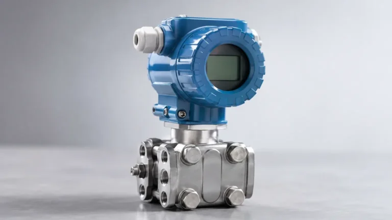
In a vented tank, a simple pressure sensor at the base can determine the level. For pressurized vessels, a differential pressure (DP) transmitter is required to subtract the headspace pressure from the total pressure at the bottom. This method is highly reliable for stable liquids but requires precise knowledge of the liquid's density.
Ultrasonic (Time-of-Flight)
Ultrasonic transmitters are non-contact devices that emit high-frequency sound waves (typically 20 kHz to 200 kHz) toward the liquid surface. The sensor measures the time it takes for the pulse to travel to the surface and reflect back. Since the speed of sound in air is known (approximately 343 m/s or 1,125 ft/s at 20°C), the distance can be calculated.
However, the speed of sound is affected by air temperature, humidity, and pressure. Most modern ultrasonic transmitters include internal temperature compensation to maintain accuracy across changing ambient conditions.
Radar (Microwave) Measurement
Radar transmitters use electromagnetic waves rather than sound waves. There are two main types:
1. Non-Contact Radar: Emits a signal through the air. It is unaffected by vacuum, high pressure, or temperature shifts, making it superior to ultrasonic technology in volatile environments.
2. Guided Wave Radar (GWR): Uses a physical probe (rod or cable) to guide the microwave signal to the liquid surface. This is particularly effective for liquids with low dielectric constants or in tanks with heavy turbulence.
Magnetic Level Transmitters
These instruments utilize a float containing an internal magnet that moves along a sensing rod or outside a bypass chamber. As the liquid level changes, the float moves, and the magnetic field triggers reed switches or a magnetostrictive sensor within the transmitter. This provides a clear physical and electronic representation of the level, often used in high-pressure or high-temperature boiler applications.
Key Evaluation Criteria for Liquid Transmitters
When specifying a transmitter liquid level solution, engineers must evaluate the chemical and physical properties of the media alongside the vessel's mechanical constraints.
Media Characteristics
* Density and Specific Gravity: Critical for hydrostatic transmitters. If the liquid density changes due to temperature fluctuations, the pressure reading will shift even if the actual level remains constant.
* Dielectric Constant ($ε_r$): Essential for radar measurement. Liquids with low dielectric constants (like oils or liquefied gases) reflect less energy, requiring more sensitive radar units or guided wave technology.
* Viscosity and Coating: Highly viscous liquids or those that crystallize can coat probes or clog pressure diaphragms. In these cases, non-contact radar or flush-diaphragm hydrostatic sensors are preferred.
* Chemical Compatibility: The wetted parts of the transmitter—such as 316L stainless steel, Hastelloy, PTFE, or PP—must be resistant to the corrosive nature of the liquid.
Environmental Factors
* Operating Pressure: Standard ultrasonic sensors are typically limited to 3 bar (43.5 psi), whereas radar and hydrostatic sensors can handle 40 bar (580 psi) or significantly higher in specialized designs.
* Temperature Ranges: High-temperature liquids (above 150°C / 302°F) often require remote-seal hydrostatic transmitters or high-temperature radar antennas with cooling fins.
* Turbulence and Foam: Surface agitation can scatter ultrasonic and non-contact radar signals. Guided wave radar or stilling wells are often employed to mitigate these effects.
Technical Selection Table
The following table provides a general comparison of common transmitter liquid measurement technologies to assist in the initial screening process.
| Technology | Measurement Type | Accuracy | Max Range (Typical) | Best For | Limitations |
| :— | :— | :— | :— | :— | :— |
| Hydrostatic | Contact (Pressure) | ±0.1% to 0.5% | 200m (656 ft) | Deep wells, vented tanks | Affected by density changes |
| Ultrasonic | Non-Contact | ±0.25% | 15m (49 ft) | Water, wastewater, acids | Affected by foam and steam |
| Guided Wave Radar | Contact (Microwave) | ±2mm to 5mm | 30m (98 ft) | Low dielectric liquids, foam | Probe can be damaged by debris |
| Non-Contact Radar | Non-Contact | ±1mm to 3mm | 100m (328 ft) | Chemicals, high temp/pressure | Higher initial cost |
| Magnetic Float | Contact | ±5mm to 10mm | 6m (20 ft) | High pressure, visual bypass | Moving parts subject to wear |
Installation Considerations
Proper installation is as critical as selecting the correct technology. Even the most advanced transmitter will fail if positioned incorrectly.
1. Nozzle Height and Diameter: For radar and ultrasonic sensors, the nozzle should be as short and wide as possible to prevent the signal from reflecting off the nozzle walls (ringing).
2. Obstruction Clearance: Transmitters should be mounted away from inlet pipes, agitators, and internal ladders. These obstructions create "false echoes" that can confuse the sensor.
3. Dead Zones (Blocking Distance): Every top-mounted transmitter has a minimum distance it cannot measure (usually 10cm to 50cm from the sensor face). Ensure the maximum liquid level does not enter this zone.
4. Submersible Anchoring: For hydrostatic transmitters used in deep wells or reservoirs, the sensor should be weighted or anchored to prevent movement caused by currents or turbulence.
For a comprehensive overview of available hardware and specific application support for these technologies, professionals may consult the Main Page of industrial instrumentation providers like Welk to review detailed product specifications.

Limitations and Common Risks
While modern transmitters are robust, certain conditions present ongoing challenges:
* Heavy Foam: Foam absorbs ultrasonic and radar signals. If thick foam is present, a hydrostatic transmitter or a guided wave radar with a coaxial probe is usually the only reliable option.
* Vacuum Conditions: Ultrasonic signals cannot travel through a vacuum. Radar or hydrostatic sensors must be used in these environments.
* Build-up: In wastewater or slurry applications, material build-up on a probe or diaphragm can cause a "level high" error. Routine maintenance or the use of non-contact sensors with high-gain antennas can reduce this risk.
Frequently Asked Questions (FAQ)
Q: How do I choose between ultrasonic and radar for liquid measurement?
A: Use ultrasonic for simple water or dilute chemical applications where cost is a primary factor and the environment is stable. Choose radar for high-accuracy requirements, pressurized tanks, or environments with significant vapor, dust, or temperature fluctuations.
Q: Can a hydrostatic transmitter measure the level of two different liquids in the same tank?
A: Only if the liquids are mixed into a consistent emulsion with a known density. If the liquids are stratified (e.g., oil over water), a hydrostatic sensor will only measure the total head pressure. To find the interface level, a Guided Wave Radar (GWR) is typically required.
Q: What is the standard output for a transmitter liquid level sensor?
A: The industry standard is a 4-20 mA analog signal, often with HART (Highway Addressable Remote Transducer) protocol superimposed for digital diagnostics. Modbus RTU (RS485) and Profibus are also common in modern networked plants.
Conclusion
Identifying the correct transmitter liquid level solution requires a balance between technical performance and cost-effectiveness. By understanding the measurement principles—whether pressure-based, acoustic, or electromagnetic—and accounting for the specific physical properties of the media, engineers can ensure long-term reliability in their level control loops. Always verify chemical compatibility and installation geometry before finalizing a system design to prevent common failure modes associated with industrial liquid processing.