Level Tank Sensor
Level Tank Sensor
In industrial process control, the selection of a level tank sensor is a critical decision that impacts safety, efficiency, and inventory management. Whether monitoring volatile chemicals, wastewater, or crude oil, understanding the underlying physics of measurement is essential for engineering a reliable system. As a professional manufacturer, Welk provides a comprehensive range of industrial level measurement instruments designed to meet the rigorous demands of modern automation.
This guide examines the primary measurement principles, selection criteria, and installation best practices for level tank sensors to assist engineers and procurement professionals in identifying the optimal solution for their specific application.
Measurement Principles of Level Tank Sensors
Before selecting a sensor, it is vital to understand how different technologies interact with the media and the tank environment. Level sensors are generally categorized into continuous measurement and point-level detection.
1. Radar Level Measurement (ToF)
Radar level sensors operate on the Time-of-Flight (ToF) principle. The sensor emits high-frequency microwave pulses (typically in the 26GHz or 80GHz range) toward the product surface. These pulses are reflected back to the antenna. The sensor measures the time elapsed between emission and reception to calculate the distance.
* Non-Contact Radar: Ideal for corrosive or hygienic applications as the sensor does not touch the media. 80GHz radar is particularly effective for small tanks due to its narrow beam angle.
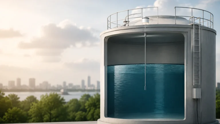
* Guided Wave Radar (GWR): Uses a probe (cable or rod) to guide the microwave signal. This is highly effective for low dielectric constants or when foam and turbulence are present.
2. Ultrasonic Level Sensors
Ultrasonic sensors also use the ToF principle but utilize sound waves instead of microwaves. The transducer emits an ultrasonic pulse that reflects off the liquid surface.
* Consideration: Because sound speed is affected by air temperature, these sensors require integrated temperature compensation. They are cost-effective for water and wastewater applications but may struggle in vacuum conditions or high-pressure environments where sound cannot propagate effectively.
3. Hydrostatic Level Transmitters
Hydrostatic measurement relies on the relationship between the height of a liquid column and the pressure exerted at the base. The formula $P = \rho \cdot g \cdot h$ (where $P$ is pressure, $\rho$ is density, $g$ is gravity, and $h$ is height) allows the sensor to determine the level based on the weight of the fluid.
* Submersible Type: Dropped directly into the tank or well.
* External Mount: Attached to the bottom or side of the tank via a flange or thread. This method is highly reliable for vented tanks with stable fluid densities.
4. Magnetic Level Gauges
Magnetic gauges use a float containing a permanent magnet that moves with the liquid level inside a bypass chamber. Outside the chamber, a series of magnetic flaps or a tracker indicates the level visually. For electronic integration, a reed chain or magnetostrictive transmitter can be added to provide a 4-20mA signal.
5. Level Switches (Point Level)
Unlike continuous sensors, level switches detect when a liquid reaches a specific height. Technologies include vibrating forks, float switches, and capacitive probes. These are essential for overfill protection and run-dry prevention for pumps.
Technical Selection Criteria
Choosing the right level tank sensor requires a detailed analysis of the process conditions. The following table provides a general comparison of common technologies used in industrial settings.
Selection Comparison Table
| Technology | Typical Accuracy | Max Temp (°C) | Max Pressure (bar) | Media Suitability | Best Use Case |
| :— | :— | :— | :— | :— | :— |
| 80GHz Radar | ±1 mm | +250°C | 40 bar | Liquids & Solids | Small tanks, high precision |
| Ultrasonic | ±0.25% FS | +80°C | 3 bar | Water, Slurries | Wastewater, open channels |
| Hydrostatic | ±0.1% to 0.5% | +100°C | 400 bar | Clean/Dirty Liquids | Deep wells, fuel tanks |
| Guided Wave Radar | ±2 mm | +450°C | 400 bar | Low Dielectric | Steam boilers, oil/water interface |
| Magnetic Gauge | ±5 mm | +400°C | 160 bar | Hazardous Liquids | Visual monitoring, high pressure |
For a broader overview of available technologies and detailed technical specifications, you may visit our Main Page to review product options and application support.
Application-Specific Engineering
Water and Wastewater Treatment
In this sector, sensors often encounter foam, steam, and varying temperatures. Ultrasonic sensors are the standard for open-air basins, while hydrostatic transmitters are preferred for deep-well pump stations. For chemical dosing tanks containing alum or bleach, non-contact radar is recommended to prevent chemical corrosion of the sensor housing.
Chemical and Petrochemical
Safety is paramount in these industries. Level tank sensors must often carry ATEX or IECEx certifications for explosive atmospheres. Guided Wave Radar (GWR) is frequently used here because it is unaffected by changes in density, pressure, or temperature, providing a stable reading even in complex hydrocarbon mixtures.
Oil and Gas
Storage tanks for crude oil often develop a layer of "bottom sediment and water" (BS&W). GWR sensors are uniquely capable of measuring both the total level and the interface level between the oil and the water, allowing for efficient separation processes.
Installation Considerations and Best Practices
Even the most advanced level tank sensor will fail if installed incorrectly. Engineers should adhere to the following guidelines:
1. Avoid the "Dead Zone": Every sensor has a blocking distance (dead zone) near the transmitter face where measurement is impossible. Ensure the sensor is mounted high enough that the maximum liquid level never enters this zone.
2. Beam Path Clearance: For radar and ultrasonic sensors, the signal spreads in a cone. Ensure there are no internal obstructions like ladders, agitators, or heating coils within the beam angle. If obstructions are unavoidable, use software-based false echo suppression.
3. Nozzle Dimensions: The mounting nozzle should be as short and wide as possible. A long, narrow nozzle can cause internal reflections that interfere with the signal, especially for ultrasonic and high-frequency radar.
4. Positioning: Do not install the sensor directly over the tank inlet. The turbulence and falling liquid will cause erratic readings and may damage the sensor over time.
5. Stilling Wells: In tanks with heavy agitation or foam, installing the sensor inside a stilling well (a vertical pipe) can provide a calm surface for more accurate measurement.

Limitations and Common Risks
* Foam: Heavy, thick foam can absorb ultrasonic and radar signals, leading to a "loss of echo." In these cases, Guided Wave Radar or hydrostatic sensors are superior.
* Vapor and Condensation: While radar can penetrate most vapors, heavy condensation on an ultrasonic transducer face can block the sound pulse. Some Welk ultrasonic sensors feature a self-cleaning face to mitigate this.
* Build-up: Sticky media can coat probes or transducers. Non-contact radar is less affected by build-up than contact-based methods like vibrating forks or GWR probes.
* Vacuum: Ultrasonic sensors cannot operate in a vacuum because sound requires a medium to travel. Radar or hydrostatic sensors must be used instead.
Frequently Asked Questions (FAQ)
Q: Can I use one sensor for different liquids?
A: It depends on the technology. Radar and ultrasonic sensors measure the surface regardless of density (as long as the dielectric constant is sufficient for radar). However, hydrostatic sensors must be recalibrated if the fluid density changes, as they measure weight, not volume.
Q: What is the difference between 26GHz and 80GHz radar?
A: 80GHz radar has a much narrower beam angle (typically 3° to 8°) compared to 26GHz (typically 10° to 20°). This makes 80GHz better for avoiding internal tank obstructions and measuring in narrow tanks.
Q: How do I handle measurement in a pressurized tank?
A: For pressurized tanks, a standard hydrostatic sensor will not work because it cannot distinguish between liquid pressure and head pressure. You must use a differential pressure (DP) transmitter or a radar sensor, which is unaffected by gas phase pressure.
Q: Is maintenance required for non-contact sensors?
A: While non-contact sensors are generally low-maintenance, they should be inspected periodically for heavy build-up on the antenna or transducer face, which can eventually degrade signal quality.
Conclusion
Selecting a level tank sensor requires balancing technical requirements with budget constraints. By understanding the measurement principles—from the precision of 80GHz radar to the rugged reliability of hydrostatic transmitters—operators can ensure long-term accuracy and safety. Welk continues to innovate in the field of industrial automation, providing customized OEM/ODM services to meet unique application challenges. For detailed technical data and to find the right instrument for your facility, explore the resources available on our Main Page.