Lift Station Sewage
Lift Station Sewage
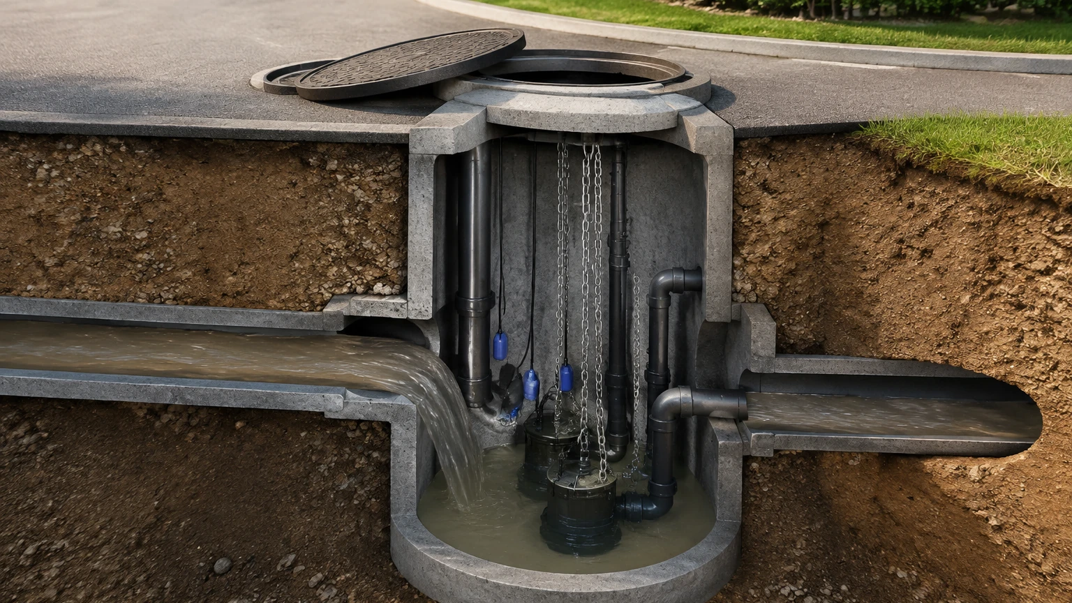
In modern wastewater management, lift stations serve as critical nodes within the collection infrastructure. These facilities are designed to move sewage from lower to higher elevations, particularly in areas where the natural topography does not allow for gravity flow or where the cost of deep trenching for gravity sewers is prohibitive. Because lift station sewage is often a complex mixture of water, organic solids, fats, oils, grease (FOG), and corrosive gases, the instrumentation used to monitor these levels must be exceptionally robust and precise.
Accurate level measurement is the primary driver for pump automation within a lift station. It ensures that pumps activate only when necessary, prevents dry-running, and provides critical high-level alarms to avoid environmental overflows. This guide examines the technical principles of level measurement in lift station sewage applications and provides engineering criteria for selecting the most effective instrumentation.
Understanding the Measurement Environment
Before selecting a sensor, it is essential to understand the unique challenges posed by lift station sewage. Unlike clean water applications, sewage wet wells are characterized by several variables that can interfere with electronic signals and mechanical components:
1. Turbulence: High-volume inflow can create surface agitation, which impacts the signal stability of non-contact sensors.
2. Foam and Scum: Biological activity and detergents often create a layer of foam. This layer can absorb ultrasonic pulses or create false echoes for certain radar frequencies.
3. Fats, Oils, and Grease (FOG): These substances tend to coat any submerged equipment, leading to mechanical failure of float switches or the clogging of pressure diaphragms.
4. Corrosive Gases: Hydrogen sulfide (H2S) is common in sewage environments. It is highly corrosive to copper, aluminum, and certain grades of stainless steel.
5. Varying Density: While sewage is primarily water, the concentration of solids can slightly alter the specific gravity, which must be accounted for in pressure-based measurements.
Measurement Principles for Lift Station Sewage
Industrial level measurement relies on several distinct physical principles. For lift station sewage, the most common methods include hydrostatic pressure, ultrasonic time-of-flight, and frequency-modulated continuous wave (FMCW) radar.
Hydrostatic Pressure Measurement
Hydrostatic level transmitters measure the pressure exerted by the liquid column above the sensor. The principle is based on the formula:
P = ρ · g · h
*(Where P is pressure, ρ is liquid density, g is gravity, and h is the height of the liquid).*
In a lift station, a submersible pressure transducer is lowered to the bottom of the wet well. The sensor converts the pressure of the sewage into an electrical signal (typically 4-20mA). To compensate for changes in atmospheric pressure, these sensors use a vented cable that allows the internal side of the diaphragm to "breathe."
* Advantages: Simple installation, relatively low cost, and unaffected by surface foam or vapor.
* Limitations: Susceptible to clogging from grease and debris. Requires periodic cleaning of the diaphragm face.
Ultrasonic (Non-Contact)
Ultrasonic sensors emit high-frequency sound pulses that reflect off the surface of the sewage. The sensor measures the time it takes for the echo to return (Time-of-Flight). Since the speed of sound in air is known, the distance to the liquid surface can be calculated.
* Advantages: No contact with the corrosive sewage, reducing maintenance requirements. Suitable for a wide range of wet well depths.
* Limitations: Sound waves can be reflected or absorbed by heavy foam. Changes in air temperature (which affect the speed of sound) require integrated temperature compensation.
Radar (FMCW)
Radar transmitters use high-frequency electromagnetic waves (often in the 26 GHz or 80 GHz range). Unlike ultrasonic waves, radar signals are unaffected by air temperature, pressure, or the presence of heavy vapors and gases. 80 GHz radar, in particular, offers a narrow beam angle, which is ideal for narrow lift stations with internal piping and ladders that might otherwise cause false reflections.
* Advantages: Extremely high accuracy, immune to H2S gas and steam, and capable of "seeing through" light foam.
* Limitations: Higher initial capital expenditure compared to hydrostatic or ultrasonic options.
Selection Criteria for Lift Station Instrumentation
Choosing the right technology requires a balance between budget, maintenance capacity, and the specific characteristics of the lift station sewage. The following table provides a comparison for engineering reference.
| Feature | Hydrostatic Transmitters | Ultrasonic Sensors | Radar (80 GHz) |
| :— | :— | :— | :— |
| Measurement Style | Contact (Submerged) | Non-Contact | Non-Contact |
| Accuracy | ±0.25% to ±0.5% | ±0.25% of range | ±1 mm to ±2 mm |
| Maintenance | High (Cleaning required) | Medium (Check for condensation) | Low |
| Foam Resistance | Excellent | Poor to Fair | Good |
| H2S Resistance | Requires specific materials | Good (Plastic housings) | Excellent (PTFE/PVDF) |
| Typical Range | 0–20 meters | 0.3–15 meters | 0.1–30+ meters |
For a comprehensive overview of available technologies and specific model specifications, engineers should consult the Main Page of professional equipment manufacturers to ensure the selected device meets local regulatory standards.
Installation Considerations
Proper installation is as critical as sensor selection. Even the most advanced radar or ultrasonic sensor will fail to provide accurate data if positioned incorrectly.
Positioning and Mounting
1. Avoid Inflow Streams: Sensors should never be mounted directly above the inlet pipe. The turbulence and falling liquid will create erratic readings and may physically damage submerged sensors.
2. Stilling Wells: In extremely turbulent lift stations, a stilling well (a vertical pipe with vent holes) can be installed. This provides a calm surface for the sensor to measure, effectively filtering out waves and foam.
3. Dead Zones: Every non-contact sensor has a "dead zone" (blocking distance) near the face of the transducer where measurement is impossible. Ensure the sensor is mounted high enough that the maximum sewage level never enters this zone.
4. Beam Path Clearance: For ultrasonic and radar sensors, the "signal beam" expands as it travels. Ensure there are no obstructions like pump power cables, brackets, or ladders within the beam's path to prevent false "high level" triggers.
Cable Management and Protection
For hydrostatic sensors, the vented cable must be protected from sharp bends or kinks, which could block the atmospheric vent tube. Using a specialized junction box with a desiccant cartridge is recommended to prevent moisture from entering the vent tube and causing internal corrosion.
Operational Risks and Limitations
When managing lift station sewage, engineers must account for the following operational risks:
* Grease Encapsulation: In stations with high FOG levels, grease can form a solid crust. This crust can support the weight of a float switch, preventing it from tipping, or it can create a physical barrier that prevents a hydrostatic sensor from sensing pressure changes.
* Power Surges: Lift stations are often located in remote areas and are susceptible to lightning strikes and power surges from heavy pump motors. Sensors should be equipped with surge protection and, where possible, isolated from the high-voltage pump circuits.
* Redundancy Requirements: For critical lift stations, a redundant measurement strategy is best practice. This often involves using a continuous level transmitter (radar or ultrasonic) for primary control and a simple, robust mechanical float switch for a secondary high-level alarm.
Frequently Asked Questions (FAQ)
Q: Why is my ultrasonic sensor reading 'full' when the wet well is nearly empty?
A: This is often caused by condensation on the sensor face or a reflection from an internal obstruction (like a ladder). In sewage environments, H2S and moisture can create droplets that scatter the ultrasonic pulse. Selecting a sensor with a "self-cleaning" or vibrating face can mitigate this, or switching to radar technology may be necessary.
Q: How often should a hydrostatic level transmitter be calibrated in a sewage application?
A: In a lift station sewage environment, it is recommended to check the zero-point calibration every 3 to 6 months. Because of the potential for grease buildup, the sensor should be physically inspected and cleaned during these intervals.
Q: Can radar sensors measure through a closed manhole cover?
A: Some specialized radar units can measure through plastic or fiberglass covers, but they cannot measure through metal. For most lift stations, the sensor is mounted inside the wet well, beneath the cover, to ensure an unobstructed signal path to the liquid surface.
Q: What is the best material for sensors in high-H2S environments?
A: For non-contact sensors, PVDF (Polyvinylidene fluoride) or PTFE (Polytetrafluoroethylene) encapsulated antennas are highly resistant to chemical attack. For submerged sensors, high-grade stainless steel (316L) or titanium is preferred, often paired with a polyurethane or FEP cable.
Conclusion and Next Steps
Effective management of lift station sewage depends on reliable data. While hydrostatic sensors offer a cost-effective solution for many standard applications, the declining cost and superior reliability of non-contact radar make it an increasingly popular choice for municipal and industrial operators.
Before proceeding with a procurement or retrofit, project managers should confirm the maximum flow rates, the expected concentration of FOG, and the physical dimensions of the wet well. For detailed technical specifications and to explore various measurement configurations, visit the Main Page to review product options and application support tailored to wastewater infrastructure.