Lift Station Sewer
Lift Station Sewer
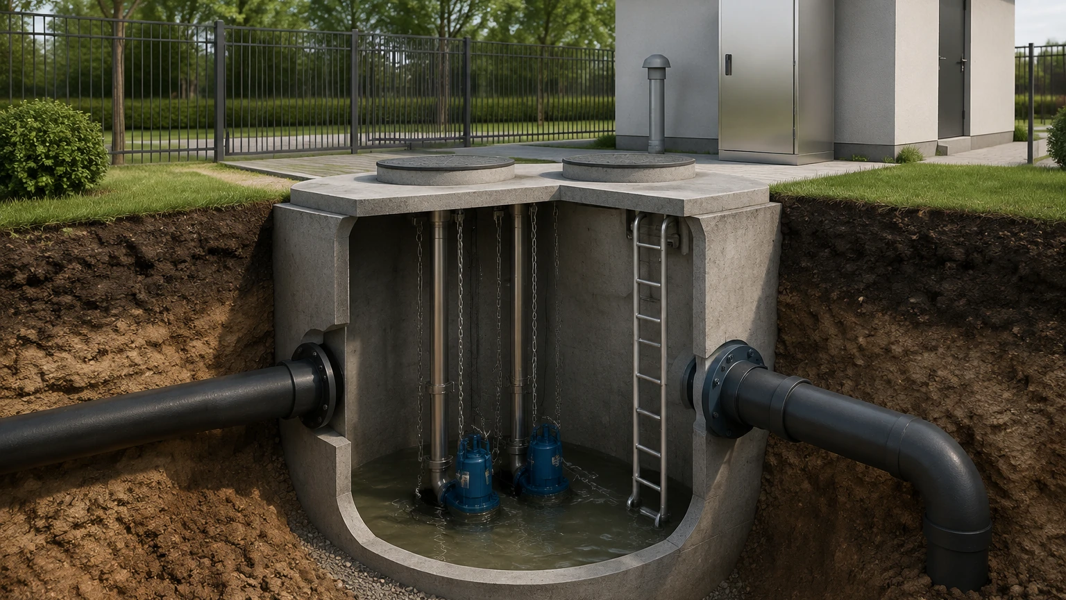
In municipal and industrial wastewater management, the lift station sewer system plays a critical role in transporting effluent to treatment facilities. Because wastewater collection systems often rely on gravity, lift stations are required whenever the elevation of the source is lower than the destination or when the distance is too great to maintain a consistent downward slope. At the heart of these stations is the wet well, where the accurate monitoring of liquid levels is essential for pump control, overflow prevention, and operational efficiency.
Selecting the appropriate level measurement technology for a lift station sewer environment requires an understanding of the unique challenges posed by wastewater, including turbulence, corrosive gases, and the presence of fats, oils, and grease (FOG). This guide examines the primary measurement principles, selection criteria, and installation best practices for engineers and plant operators.
Measurement Principles for Sewer Lift Stations
Level measurement in a lift station sewer generally falls into two categories: contact and non-contact. Each technology utilizes different physical principles to determine the height of the wastewater in the wet well.
1. Ultrasonic Level Measurement (Non-Contact)
Ultrasonic sensors emit high-frequency sound pulses that travel through the air, reflect off the surface of the liquid, and return to the transducer. The sensor calculates the distance based on the time-of-flight (ToF) of the sound wave.
* Principle: $Distance = (Speed of Sound \times Time) / 2$.
* Suitability: This is a common choice for lift stations due to its non-contact nature, which reduces maintenance requirements. However, it can be affected by heavy foam, which absorbs sound waves, or significant temperature fluctuations that change the speed of sound.
2. Radar Level Measurement (Non-Contact)
Radar sensors, specifically Frequency Modulated Continuous Wave (FMCW) or pulse radar, use microwave signals instead of sound waves. These electromagnetic waves are emitted toward the liquid surface and reflected back.
* Principle: Unlike sound, microwaves are unaffected by air temperature, vacuum, or pressure changes. They penetrate foam and steam more effectively than ultrasonic waves.
* Suitability: Radar is increasingly preferred for lift station sewer applications where high accuracy is required despite the presence of vapors or turbulent surfaces.
3. Hydrostatic Pressure Measurement (Contact)
Hydrostatic transmitters are submerged at the bottom of the wet well. They measure the pressure exerted by the liquid column above the sensor diaphragm.
* Principle: $P = \rho \times g \times h$, where $P$ is pressure, $\rho$ is liquid density, $g$ is gravity, and $h$ is the height of the liquid.
* Suitability: These sensors provide a direct measurement regardless of surface conditions like foam. However, in a sewer environment, the diaphragm can become coated with grease or debris, requiring periodic cleaning.
4. Float Switches (Point Level)
Float switches are mechanical devices that rise and fall with the water level. When the float reaches a certain angle, an internal microswitch or mercury switch triggers.
* Principle: Mechanical buoyancy.
* Suitability: While not suitable for continuous level monitoring, they are indispensable as redundant high-level alarms or low-level pump cut-offs in lift station sewer designs.
Technology Selection Criteria
Choosing the right instrument for a lift station sewer depends on the specific characteristics of the influent and the physical constraints of the wet well. The following table provides a comparison of the most common technologies.
| Feature | Ultrasonic | Radar | Hydrostatic | Float Switches |
| :— | :— | :— | :— | :— |
| Measurement Type | Continuous (Non-contact) | Continuous (Non-contact) | Continuous (Contact) | Point Level (Contact) |
| Accuracy | High (±0.25% of range) | Very High (±2mm to ±5mm) | Moderate (±0.5% of span) | Low |
| Effect of Foam | Significant interference | Minimal interference | No effect | No effect |
| Effect of Grease | No effect (non-contact) | No effect (non-contact) | High (can clog sensor) | Moderate (buildup risk) |
| Maintenance | Low | Very Low | Moderate | Moderate |
| Typical Cost | Moderate | High | Moderate | Low |
Practical Engineering Considerations for Lift Stations
When designing the instrumentation layout for a lift station sewer, several environmental factors must be addressed to ensure long-term reliability.
Hydrogen Sulfide (H2S) Corrosion
Sewer environments are often rich in hydrogen sulfide gas, which is highly corrosive to electronics and metals. Level sensors used in these areas should have high-grade housing materials, such as PVDF, PP, or 316L stainless steel. For non-contact sensors, ensuring the transducer face is chemically resistant is vital.
Fats, Oils, and Grease (FOG)
FOG is a major challenge in lift station sewer maintenance. In wet wells, grease often forms a thick layer on the surface or clings to the walls.
* Non-contact sensors (Radar/Ultrasonic) are generally immune to grease on the liquid surface, but they must be positioned to avoid "seeing" grease buildup on the side walls.
* Contact sensors (Hydrostatic) should be installed with a flushing ring or positioned in an area with enough flow to prevent stagnant grease from encrusting the diaphragm.
Turbulence and Inflow
The entry of wastewater into the wet well can create significant turbulence and splashing. If a sensor is positioned directly under an inflow pipe, the readings will be erratic. A stilling well—a vertical pipe with vent holes—can be used to provide a calm surface for the sensor to measure, though these require regular cleaning to prevent solids from clogging the pipe.
Installation Guidelines
Proper installation is as important as technology selection. For a typical lift station sewer with a depth of 5 to 10 meters (16.4 to 32.8 ft), follow these steps:
1. Avoid Dead Zones: Every non-contact sensor has a "dead zone" or "blocking distance" near the transducer face (typically 0.2m to 0.5m). Ensure the sensor is mounted high enough that the maximum water level never enters this zone.
2. Beam Angle Clearance: Radar and ultrasonic signals spread out in a cone. Ensure there are no obstructions, such as ladders, pumps, or pipes, within this beam path. For a sensor with a 10-degree beam angle at a depth of 6 meters (19.7 ft), the beam diameter at the bottom will be approximately 1 meter (3.3 ft).
3. Vertical Alignment: The sensor must be mounted perfectly perpendicular to the liquid surface. Even a few degrees of tilt can cause the signal to reflect away from the receiver, leading to signal loss.
4. Submersible Sensor Placement: If using hydrostatic transmitters, do not rest the sensor on the very bottom where silt and sludge accumulate. Suspend it approximately 150mm to 300mm (6 to 12 inches) above the floor.
Limitations and Common Risks
Despite advancements in technology, certain risks remain inherent to lift station sewer monitoring:
* Signal Absorption by Foam: In stations where detergents are prevalent, thick foam can act as an insulator for ultrasonic waves. In these cases, 80GHz radar is the recommended upgrade.
* Condensation: In humid wet wells, condensation can form on the face of non-contact transducers. Many modern sensors feature "drip-off" designs or specialized coatings to prevent water droplets from attenuating the signal.
* Data Spikes: Rapid changes in level due to pump start-up can cause momentary fluctuations. Modern transmitters allow for "damping" settings, which average the readings over a few seconds to provide a stable output for the PLC or SCADA system.
For engineers looking to compare specific models or explore customized OEM options for their wastewater infrastructure, the Main Page offers detailed technical specifications and application support for a wide range of industrial level meters.
Frequently Asked Questions (FAQ)
Q: How often should level sensors in a sewer lift station be calibrated?
A: For non-contact sensors, an annual check is usually sufficient unless there is a significant change in the process. Hydrostatic sensors may require semi-annual checks to ensure grease buildup hasn't caused a zero-shift in the pressure reading.
Q: Can I use a radar sensor in a confined space like a manhole?
A: Yes. High-frequency radar (such as 80GHz) has a very narrow beam angle, making it ideal for narrow manholes or wet wells with many internal obstructions.
Q: What is the best backup for a continuous level sensor?
A: High-level float switches are the industry standard. They provide a simple, independent mechanical trigger that can activate an alarm or a secondary pump even if the primary electronic sensor or PLC fails.
Q: Does the density of the sewage affect the measurement?
A: For ultrasonic and radar, no. For hydrostatic pressure sensors, yes. If the density of the wastewater changes significantly (e.g., due to high solids content), the pressure-to-level conversion will need to be adjusted accordingly.
Conclusion
Maintaining a reliable lift station sewer system hinges on accurate level data. While ultrasonic sensors remain a cost-effective standard, the shift toward radar technology offers improved reliability in harsh, foamy, or vapor-heavy environments. By considering the chemical composition of the waste, the physical layout of the wet well, and the necessary maintenance cycles, operators can select a measurement solution that minimizes downtime and prevents environmental hazards. For professional guidance on selecting the right instrument for your specific application, you may Review product options and application support to find the most suitable technology for your project requirements.