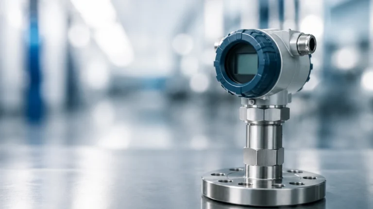
Liquicap
Liquicap
In the field of industrial automation, accurate level measurement is a cornerstone of process safety, efficiency, and inventory management. Among the various technologies available, capacitive level measurement—often referred to in the context of Liquicap probes—stands out for its versatility and reliability in both simple and complex liquid applications. This technology utilizes the electrical property of capacitance to determine the height of a liquid within a vessel, offering a solution that is robust enough to handle high temperatures, high pressures, and chemically aggressive media.
As a professional manufacturer of industrial level measurement instruments, Welk provides a range of solutions including radar, ultrasonic, and capacitive sensors. Understanding the technical nuances of Liquicap technology is essential for engineers and plant managers who must select the most appropriate instrumentation for their specific process conditions. This guide provides a comprehensive technical overview of capacitive level measurement, from its fundamental physics to practical installation considerations.
Understanding the Capacitive Level Measurement Principle
The operation of a Liquicap probe is based on the principle of a variable capacitor. In its simplest form, a capacitor consists of two conductive plates separated by an insulating material known as a dielectric. The ability of this setup to store an electrical charge is defined as capacitance (C), which is governed by the formula:
**C = ε₀ * εᵣ * (A / d)**
Where:
- ε₀ is the permittivity of free space (a constant).
- εᵣ is the relative dielectric constant of the material between the plates.
- A is the surface area of the plates.
- d is the distance between the plates.
In an industrial tank application, the Liquicap probe (or electrode) acts as one plate of the capacitor, while the tank wall (if metallic and grounded) acts as the second plate. If the tank is non-metallic, a second reference electrode or a grounding rod is required. The space between the probe and the wall is filled with either the process liquid or the gas/air above it.
Since the geometry of the installation (the area A and distance d) remains constant, the capacitance becomes a function of the dielectric constant (εᵣ) of the medium between the electrodes. Because most liquids have a significantly higher dielectric constant than air (εᵣ ≈ 1), the total capacitance increases linearly as the liquid level rises and covers more of the probe. The electronics integrated into the sensor head convert this change in capacitance into a proportional 4-20 mA DC or digital signal.
Key Components and Construction of Liquicap Probes
Liquicap sensors are engineered to withstand harsh environments, and their construction reflects the diversity of industrial needs. The primary components include:
1. The Electrode (Probe)
Probes are typically made from stainless steel (e.g., 316L) and can be designed as rigid rods for shorter distances or flexible ropes for tall silos and tanks. Rod probes are generally used for heights up to 4 meters, while rope probes can extend up to 20 meters or more.
2. Insulation
For conductive liquids, the probe must be fully insulated with a material like PTFE (Polytetrafluoroethylene) or PFA (Perfluoroalkoxy). This insulation prevents a short circuit between the electrode and the liquid. For non-conductive liquids (such as oils), an uninsulated probe may be used, though insulation is often preferred for added chemical resistance and to prevent accidental shorting if moisture enters the system.
3. The Electronic Insert
The housing, usually made of aluminum or stainless steel, contains the signal processing electronics. These components must be capable of filtering out electrical noise and compensating for temperature fluctuations to ensure a stable output.
4. Process Connection
Standard threaded connections (e.g., G½", NPT) or flanged connections are used to mount the probe to the vessel. These connections must provide a pressure-tight seal, often rated up to 100 bar or higher depending on the model.
Selection Criteria for Capacitive Level Sensors
Choosing the right Liquicap configuration requires a detailed analysis of the process media and the vessel geometry. The following factors are critical:
Dielectric Constant (εᵣ)
The dielectric constant of the liquid is the most important factor. Conductive liquids (water-based, εᵣ > 20) are generally easier to measure because the capacitance change is large. Non-conductive liquids (hydrocarbons, εᵣ < 5) require more sensitive electronics and a stable reference electrode to ensure accuracy.
Conductivity
If the liquid is conductive, a fully insulated probe is mandatory. If the liquid is non-conductive but prone to moisture contamination, insulation is still recommended to maintain measurement integrity.
Vessel Material
In metallic tanks, the wall serves as the ground reference. In plastic, glass, or concrete tanks, a concentric shield or a separate grounding rod must be installed alongside the probe to complete the electrical circuit.
Temperature and Pressure
Capacitive sensors are excellent for extreme conditions. Standard models can handle temperatures from -40°C to +200°C, with specialized versions reaching even higher. Pressure ratings must be matched to the vessel's maximum operating pressure.
Practical Selection Table
To assist in the engineering phase, the following table summarizes the typical application ranges for different capacitive probe types:
| Probe Type | Medium Type | Tank Type | Max Length | Typical Application |
| :— | :— | :— | :— | :— |
| Insulated Rod | Conductive/Corrosive | Metallic/Non-metallic | 4m | Chemical storage, water treatment |
| Non-insulated Rod | Non-conductive (Oil) | Metallic | 4m | Fuel tanks, hydraulic oil |
| Insulated Rope | Conductive | Large Metallic Silos | 20m+ | Large scale process tanks |
| Concentric Shield | Low Dielectric Liquids | Any | 2m | Small laboratory tanks, high accuracy oil measurement |
| High-Temp Probe | Any | Metallic | 4m | Steam boilers, hot resin reactors |

Installation Guidelines and Best Practices
Proper installation is vital for the performance of a Liquicap system. Failure to follow engineering best practices can lead to signal instability or measurement errors.
1. Avoid Obstructions: The probe should be installed at a distance from the tank wall and internal structures (like ladders or agitators) to prevent interference with the electromagnetic field. A minimum distance of 100mm from the wall is usually recommended.
2. Grounding: Ensure a low-resistance electrical connection between the sensor housing and the metallic tank. If the tank is coated with an insulating liner, a dedicated grounding strap to the process liquid or a reference electrode is necessary.
3. Dead Zones: Every probe has a "dead zone" at the top and bottom where measurement is not possible due to the mechanical construction of the mounting and the weight at the end of the rope. These must be accounted for in the control system scaling.
4. Still Wells: In tanks with heavy turbulence or foam, installing the Liquicap probe inside a stilling well (a bypass pipe) can stabilize the liquid surface and provide a consistent ground reference, improving accuracy.
5. Nozzle Height: The probe should extend beyond the mounting nozzle into the tank. If the nozzle is too long, it can create a localized capacitance area that does not reflect the actual tank level.
Limitations and Mitigation Strategies
While Liquicap technology is highly versatile, it is not without limitations. Understanding these helps in designing a more resilient system.
* Build-up and Coating: If a conductive liquid leaves a coating on the insulated probe as the level drops, the sensor may continue to detect the coating and report a false high level. Mitigation: Use sensors with "Active Shield" technology or frequency-shift electronics that can distinguish between a thick coating and the actual liquid level.
* Changes in Dielectric Constant: If the composition of the liquid changes significantly (e.g., switching from an oil-based to a water-based process in the same tank), the sensor will require recalibration. Mitigation: Use a second reference probe to compensate for εᵣ changes in real-time.
* Vapor Phase Interference: In high-pressure steam applications, the dielectric constant of the vapor phase can increase, affecting the measurement. Mitigation: Specialized high-pressure electronics are required to compensate for the vapor phase density.
Common Industrial Applications
Liquicap probes are utilized across a broad spectrum of industries due to their lack of moving parts and high durability:
* Chemical Processing: Measuring aggressive acids and alkalis where non-contact sensors might struggle with vapor or foam.
* Oil and Gas: Monitoring separator levels and fuel storage where high pressure and low dielectric constants are common.
* Food and Beverage: Level control in storage tanks for syrups, oils, and water, provided the materials meet hygienic standards.
* Power Generation: Monitoring condensate tanks and boiler feedwater levels.
For engineers seeking a comprehensive range of industrial instrumentation, visiting the Main Page provides access to technical specifications and support for various level measurement technologies, including radar and ultrasonic alternatives that may complement capacitive systems in complex plants.
Frequently Asked Questions (FAQ)
Q: Can Liquicap be used for solids or powders?
A: While specifically designed for liquids, capacitive technology can be used for solids (often called Solicap). However, the calibration is different because solids have significant air gaps between particles, affecting the bulk dielectric constant.
Q: Does the probe need to be calibrated on-site?
A: Yes, most capacitive sensors require a "dry" (0%) and "wet" (100%) calibration after installation to account for the specific vessel geometry and the dielectric properties of the medium.
Q: What happens if the probe touches the tank wall?
A: If an uninsulated probe touches a metallic wall, it will short circuit. If an insulated probe touches the wall, it will create a localized high-capacitance point, resulting in significant measurement errors. Probes must be installed straight and secured against swaying.
Q: Is Liquicap suitable for hygienic applications?
A: Yes, many probes are available with FDA-listed materials like PTFE and PFA and hygienic process connections (Tri-Clamp), making them suitable for the food and pharmaceutical industries.
By adhering to these technical principles and selection guidelines, process engineers can successfully implement Liquicap technology to achieve precise and maintenance-free level measurement in nearly any liquid environment. For further technical documentation and product selection tools, professionals are encouraged to review product options and application support on the Welk Main Page.