Digital Pressure Transmitter
Digital Pressure Transmitter
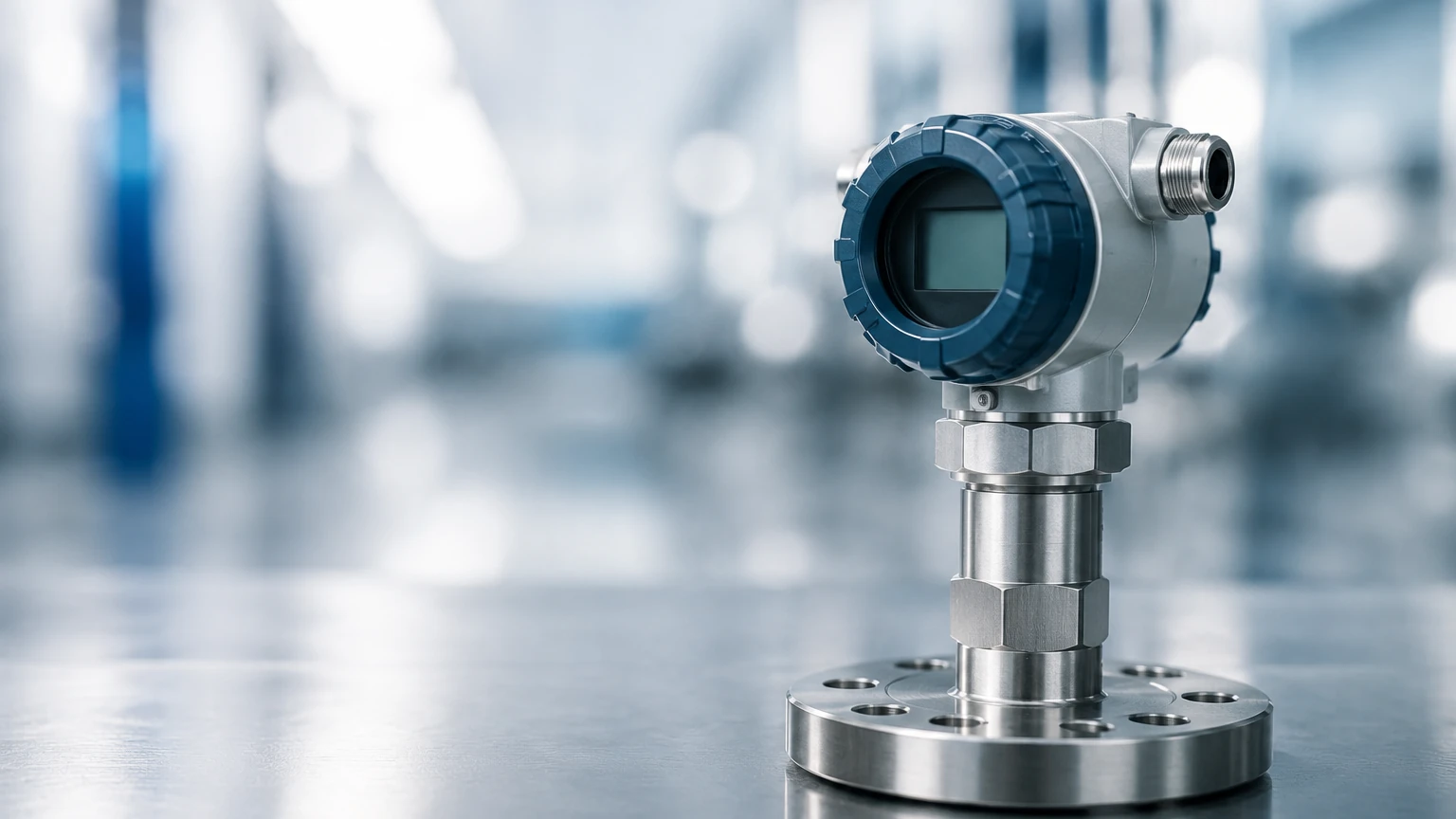
In the landscape of industrial process control, the digital pressure transmitter serves as a fundamental component for monitoring both fluid pressure and, by extension, liquid levels through hydrostatic principles. Unlike traditional analog instruments that rely solely on continuous voltage or current loops, a modern digital pressure transmitter integrates advanced microprocessors to convert physical force into high-precision data. This transition to digital technology has significantly improved accuracy, long-term stability, and the ability to perform remote diagnostics in complex industrial environments.
For engineers and plant operators, understanding the nuances of these instruments is critical for maintaining system integrity. Whether applied in water treatment, chemical processing, or oil and gas, the selection of a digital pressure transmitter requires a deep dive into its measurement physics, digital communication protocols, and mechanical constraints.
Understanding Measurement Principles
The primary function of a digital pressure transmitter is to sense the force exerted by a fluid (liquid or gas) against a sensing element and translate that force into a digital signal. In level measurement applications, this is typically achieved through the hydrostatic pressure principle.
The Hydrostatic Principle
Hydrostatic level measurement is based on the relationship between the height of a liquid column and the pressure it exerts at the base. The formula used is:
P = ρ × g × h
* P: Hydrostatic pressure (typically measured in bar or kPa).
* ρ (Rho): Density of the liquid (kg/m³).
* g: Gravitational acceleration (approximately 9.81 m/s²).
* h: Height of the liquid column (meters).
Because gravity and density (assuming a stable temperature) are constants, the pressure measured by the digital pressure transmitter is directly proportional to the liquid level. The digital processor within the transmitter then scales this pressure value into a level reading, often outputting it via a 4-20mA signal with a HART overlay or a pure digital protocol like Modbus RS485.
Sensor Technologies
Most digital transmitters utilize one of two primary sensing technologies:
1. Piezoresistive Sensors: These consist of a diaphragm with strain gauges diffused into a silicon or ceramic substrate. As pressure deforms the diaphragm, the electrical resistance changes. The digital electronics then compensate for temperature-induced errors using internal lookup tables.
2. Capacitive Sensors: These measure the change in capacitance between a sensing diaphragm and fixed electrode plates. They are known for high sensitivity and excellent overpressure protection.
Key Features of Modern Digital Pressure Transmitters
The "digital" aspect of these transmitters refers to more than just the display. It encompasses the internal signal processing and the communication capabilities that distinguish them from legacy devices.
* High-Resolution ADCs: Modern units utilize 16-bit or 24-bit Analog-to-Digital Converters (ADCs) to ensure that the subtle nuances of pressure changes are captured without losing data to quantization noise.
* Smart Compensation: Digital transmitters perform real-time compensation for ambient temperature changes and non-linearity of the sensor element. This results in a much lower Total Probable Error (TPE) compared to analog counterparts.
* Multi-Variable Output: Many digital units can transmit multiple variables simultaneously, such as process pressure, sensor temperature, and calculated level or volume.
* Remote Configuration: Through protocols like HART, Profibus, or Foundation Fieldbus, technicians can calibrate, range, and diagnose the instrument from a control room, eliminating the need for hazardous field adjustments.
Technical Selection Criteria for Industrial Applications
Selecting the correct digital pressure transmitter involves balancing process requirements with environmental constraints. The following table provides a practical reference for common selection parameters.
Selection Reference Table
| Parameter | Specification Range / Options | Application Consideration |
| :— | :— | :— |
| Measurement Type | Gauge, Absolute, Differential | Gauge is standard for vented tanks; Differential for pressurized tanks. |
| Measuring Range | 0–100 mbar to 0–600 bar | Ensure the operating pressure falls within 25%–75% of the sensor range. |
| Accuracy Class | 0.05%, 0.075%, 0.1% FS | Higher accuracy is required for custody transfer or precise dosing. |
| Wetted Materials | SS316L, Hastelloy C, Tantalum | Must be chemically compatible with the process media. |
| Output Protocol | 4-20mA HART, RS485 Modbus, CANopen | Must match the existing PLC/DCS architecture. |
| Process Temp. | -40°C to +125°C (Standard) | Use remote seals or siphons for high-temperature steam applications. |
| Ingress Protection | IP65, IP67, IP68 | IP68 is mandatory for submersible or flood-prone installations. |
When evaluating these specifications, it is often helpful to consult a comprehensive technical resource. For a detailed overview of how these instruments integrate into broader level measurement systems, engineers can visit the Main Page to review product options and application support.
Installation and Engineering Best Practices
The reliability of a digital pressure transmitter is heavily dependent on the quality of its installation. Even the most accurate digital sensor will provide erroneous data if mechanical installation errors are present.
Mounting and Orientation
For liquid applications, the transmitter should ideally be mounted below the process tap to ensure the impulse lines remain filled with liquid and free of trapped air. Conversely, for gas applications, the transmitter should be mounted above the tap so that any condensate drains back into the process line.
Impulse Piping
Impulse lines should be as short as possible to minimize lag and potential clogging. A slope of at least 1:12 is recommended to facilitate the venting of air or drainage of liquids. For highly viscous or corrosive media, a diaphragm seal (chemical seal) should be used to isolate the transmitter’s internal sensing element from the process.
Zero-Point Calibration
After installation, a "field zero" should be performed. Atmospheric pressure and the mounting position (orientation) can cause a slight offset in the sensor. Digital transmitters allow for a simple digital zero-trim, which aligns the instrument's zero reference with the actual installation conditions without affecting the span.
Limitations and Operational Challenges
While highly versatile, digital pressure transmitters are not universal solutions. Engineers must account for the following limitations:
1. Density Sensitivity: In level measurement, any change in the liquid's specific gravity (due to temperature fluctuations or chemical concentration changes) will result in a level error. If the density decreases, the pressure at the bottom drops, and the transmitter will report a lower level than actually exists.
2. Clogging and Coating: In wastewater or slurry applications, the small process ports of a standard transmitter can become clogged. In these instances, flush-diaphragm transmitters or non-contact methods like radar may be more appropriate.
3. Overpressure Events: While digital sensors have high burst pressures, repeated pressure spikes (water hammer) can fatigue the diaphragm, leading to drift or permanent failure. Installing a pressure snubber is a common mitigation strategy.
4. Electronic Interference: Although digital signals are more robust than analog, high-frequency electromagnetic interference (EMI) from variable frequency drives (VFDs) can still affect the internal ADC. Shielded cabling and proper grounding are essential.
Frequently Asked Questions (FAQ)
Q: What is the difference between a gauge pressure transmitter and an absolute pressure transmitter?
A: A gauge pressure transmitter measures pressure relative to the local atmospheric pressure. An absolute pressure transmitter measures pressure relative to a full vacuum. In most vented tank level applications, gauge pressure is used because the atmosphere exerts equal pressure on both the liquid surface and the transmitter's reference port.
Q: Can a digital pressure transmitter be used for steam applications?
A: Yes, but the sensitive electronics must be protected from high temperatures. A pigtail siphon or a water-filled buffer tube should be installed to ensure that only cooled condensate, rather than live steam, comes into contact with the transmitter diaphragm.
Q: How often should a digital pressure transmitter be calibrated?
A: Most modern digital units have a stability specification that allows for calibration intervals of 2 to 5 years. However, critical safety loops or highly corrosive environments may require annual verification.
Q: Is HART communication the same as a digital output?
A: HART (Highway Addressable Remote Transducer) is a hybrid protocol. It superimposes a digital signal on top of a standard 4-20mA analog loop. This allows for digital configuration and diagnostics while remaining compatible with legacy analog control systems.
Conclusion
The digital pressure transmitter remains a cornerstone of industrial automation, providing a reliable and cost-effective means of measuring pressure and level across diverse sectors. By leveraging microprocessor-based compensation and digital communication, these devices offer a level of precision and diagnostic depth that was previously unattainable. Success in deployment, however, requires careful attention to the chemical nature of the media, the physical constraints of the installation site, and the inherent limitations of hydrostatic measurement. For professionals seeking to optimize their process loops, selecting a high-quality instrument backed by robust technical support is the first step toward operational excellence.