Liquid Fertilizer Flow Monitor
Liquid Fertilizer Flow Monitor
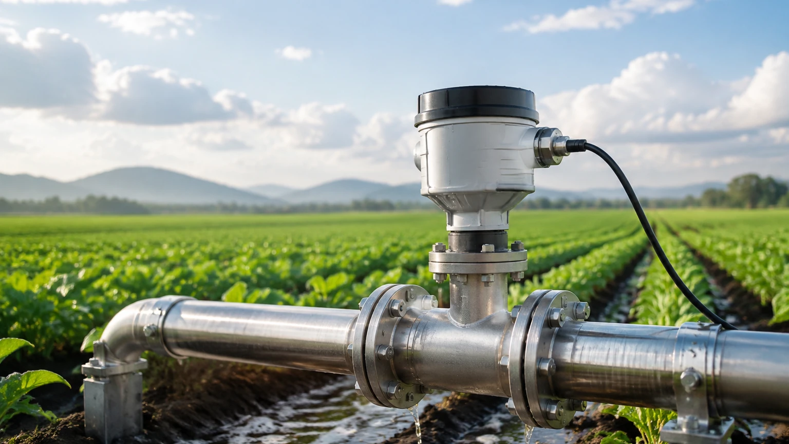
In modern industrial agriculture and chemical processing, the precise application of nutrients is a critical factor in both economic efficiency and environmental stewardship. A liquid fertilizer flow monitor serves as the primary diagnostic tool for ensuring that application rates match prescription maps or process requirements. Whether integrated into a field sprayer, a fertigation system, or an industrial blending line, these monitors provide real-time data that prevents over-application—which can lead to crop damage and groundwater contamination—and under-application, which results in diminished yields.
For engineers and facility managers, selecting the correct monitoring technology requires a deep understanding of the chemical properties of the fertilizer, the physical constraints of the piping system, and the required data integration protocols. This article explores the technical principles, selection criteria, and installation best practices for liquid fertilizer flow monitoring systems.
Measurement Principles for Liquid Fertilizers
Liquid fertilizers are often complex solutions containing nitrogen, phosphorus, and potassium (NPK) in various concentrations. These fluids can be highly corrosive, viscous, or contain suspended solids. Consequently, several different measurement principles are employed depending on the specific fluid characteristics.
Electromagnetic Flow Measurement (Magmeters)
Electromagnetic flow meters operate on Faraday’s Law of Induction. When a conductive liquid (like most liquid fertilizers) flows through a magnetic field, it generates a voltage proportional to its velocity.
* Advantages: No moving parts to wear out, negligible pressure drop, and high accuracy (typically ±0.5%).
* Requirements: The liquid must have a minimum conductivity, usually >5 μS/cm. Since liquid fertilizers are mineral-based salt solutions, they are excellent candidates for this technology.
Ultrasonic Flow Measurement
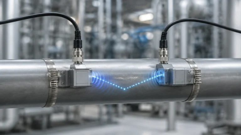
Ultrasonic monitors use sound waves to determine flow velocity. There are two primary types: Transit-time and Doppler.
* Transit-time: Measures the time difference between signals sent upstream and downstream. This is best for clean, filtered liquid fertilizers.
* Doppler: Measures the frequency shift of signals reflected off particles or bubbles. This is preferred for "slurry" style fertilizers or those with significant particulate matter.
Turbine and Paddlewheel Meters
These are mechanical meters where the fluid flow rotates a turbine or a wheel. The rotational speed is proportional to the flow rate.
* Advantages: Lower initial cost and simple integration.
* Limitations: Moving parts are susceptible to wear from abrasive particles and can be damaged by chemical corrosion if the materials (e.g., bearings and shafts) are not specifically rated for fertilizer contact.
Key Evaluation Criteria for Equipment Selection
Choosing a liquid fertilizer flow monitor involves balancing precision with durability. The following factors should be confirmed during the procurement phase:
1. Chemical Compatibility
Fertilizers such as UAN (Urea Ammonium Nitrate) or phosphoric acid can be highly aggressive toward standard metals. Monitoring equipment should utilize chemically resistant liners and electrodes. Common materials include:
* Liners: PTFE (Teflon), PFA, or EPDM.
* Electrodes/Hardware: 316L Stainless Steel, Hastelloy C, or Titanium.
2. Flow Range and Turn-down Ratio
The monitor must be sized not just for the pipe diameter, but for the actual flow velocity. A typical electromagnetic monitor performs best between 0.3 m/s and 10 m/s (approx. 1 ft/s to 33 ft/s). If the flow is too slow, the signal-to-noise ratio decreases, leading to inaccuracies.
3. Output and Integration
For B2B industrial applications, the monitor must communicate with a PLC (Programmable Logic Controller) or a SCADA system. Common outputs include:
* 4-20mA Analog: Standard for real-time flow rate monitoring.
* Pulse/Frequency: Used for totalization (measuring the total volume of fertilizer applied).
* Digital Protocols: RS485 Modbus or CAN bus for advanced diagnostics.
Selection Table: Technology Comparison
| Technology | Accuracy | Conductivity Required? | Moving Parts | Best For |
| :— | :— | :— | :— | :— |
| Electromagnetic | High (±0.5%) | Yes | No | High-volume, corrosive conductive fluids |
| Ultrasonic | Moderate (±1-2%) | No | No | Non-invasive retrofitting on existing pipes |
| Turbine | Moderate (±1%) | No | Yes | Clean liquids, low-budget applications |
| Coriolis | Very High (±0.1%)| No | No | Mass-flow measurement and high-viscosity fluids |
Installation and Maintenance Considerations
To ensure the liquid fertilizer flow monitor provides reliable data, strict adherence to installation geometry is required.
Piping Geometry
Most flow monitors require a "straight run" of pipe before and after the sensor to stabilize the flow profile. A common rule of thumb is 10D upstream and 5D downstream (where D is the pipe diameter). For a 50 mm (2 inch) pipe, this means 500 mm of straight pipe before the meter and 250 mm after it. Failure to provide this results in turbulence that the sensor may misinterpret as fluctuating flow.
Orientation and Air Entrainment
The sensor should always be installed in a section of pipe that remains full of liquid. In horizontal runs, avoid the highest point where air bubbles might collect. Ideally, the monitor should be installed in a vertical pipe with the flow moving upward. This ensures the pipe is completely full and prevents air pockets from interfering with the measurement.
Maintenance Protocols
Liquid fertilizers can "salt out" or create scale buildup during periods of inactivity.
* Flushing: Systems should be flushed with water after every use to prevent crystallization inside the flow tube.
* Zero-Point Calibration: Periodically check the "zero" flow reading when the pumps are off and the pipe is full to ensure there is no electronic drift.
Common Risks and Limitations
While modern monitors are robust, certain conditions can lead to failure:
1. Empty Pipe Detection: If a monitor is not equipped with empty pipe detection, it may generate erratic signals when the fertilizer tank runs dry, leading to false data in the control system.
2. Electrode Coating: In electromagnetic meters, certain additives in the fertilizer can coat the electrodes over time, insulating them and causing the signal to fail.
3. Pressure Spikes: Rapidly closing valves can cause water hammer, which may damage the internal liners of high-end flow monitors.
For comprehensive fluid management, flow monitoring is often paired with level measurement in the primary storage tanks. This allows for a mass-balance check—comparing how much the tank level has dropped against how much the flow monitor has recorded. As a professional manufacturer of industrial level measurement instruments, Welk provides the necessary radar and ultrasonic level sensors to complement these systems. To explore integrated solutions for tank management and fluid monitoring, you can Review product options and application support on our main site.
Frequently Asked Questions (FAQs)
Q: Can I use a standard water flow meter for liquid fertilizer?
A: Generally, no. Standard water meters often use brass or low-grade stainless steel which will corrode rapidly when exposed to nitrogen-based fertilizers. Always verify that the wetted materials are compatible with your specific chemical profile.
Q: How do I handle fertilizers with high solid content?
A: For fertilizers that contain suspended solids or are delivered as a slurry, electromagnetic meters or Doppler-style ultrasonic meters are the best choices, as they do not have internal obstructions that can clog.
Q: What is the typical lifespan of a liquid fertilizer flow monitor?
A: With proper flushing and material selection, an electromagnetic monitor can last 10 to 15 years in an industrial environment. Mechanical meters typically require service or replacement every 2 to 5 years depending on the abrasiveness of the fluid.
Q: Does the viscosity of the fertilizer affect the reading?
A: For electromagnetic and ultrasonic transit-time meters, viscosity has a negligible effect as long as the flow remains within the rated velocity range. However, for turbine or variable area meters, changes in viscosity can significantly alter the calibration constant.
By understanding these technical nuances, B2B stakeholders can implement monitoring solutions that enhance process transparency and ensure the long-term reliability of their nutrient delivery systems.