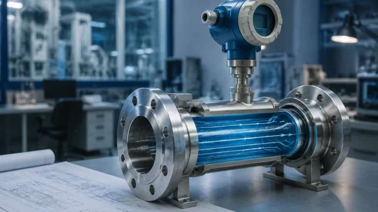
Liquid Float Switch
Liquid Float Switch
In the landscape of industrial automation and process control, the liquid float switch remains one of the most reliable and cost-effective methods for point-level detection. Despite the rise of high-tech non-contact sensors, the fundamental physics of buoyancy utilized by float switches provides a level of certainty that is essential for critical overflow protection, pump control, and low-level alarms. Welk, a specialist in industrial level measurement, provides a range of these instruments designed to withstand the rigors of chemical processing, water treatment, and oil and gas applications.
Selecting the correct liquid float switch requires a deep understanding of the fluid dynamics, chemical compatibility, and the mechanical requirements of the vessel. This guide serves as a practical engineering reference for selecting, installing, and maintaining float-based level switches in professional B2B environments.
Measurement Principles and Internal Mechanisms
The operation of a liquid float switch is governed by Archimedes' principle, which states that a body immersed in a fluid is buoyed up by a force equal to the weight of the fluid displaced by the body. In a float switch, a buoyant component (the float) moves vertically or in an arc as the liquid level rises and falls. This mechanical movement is then converted into an electrical signal.
Reed Switch Technology
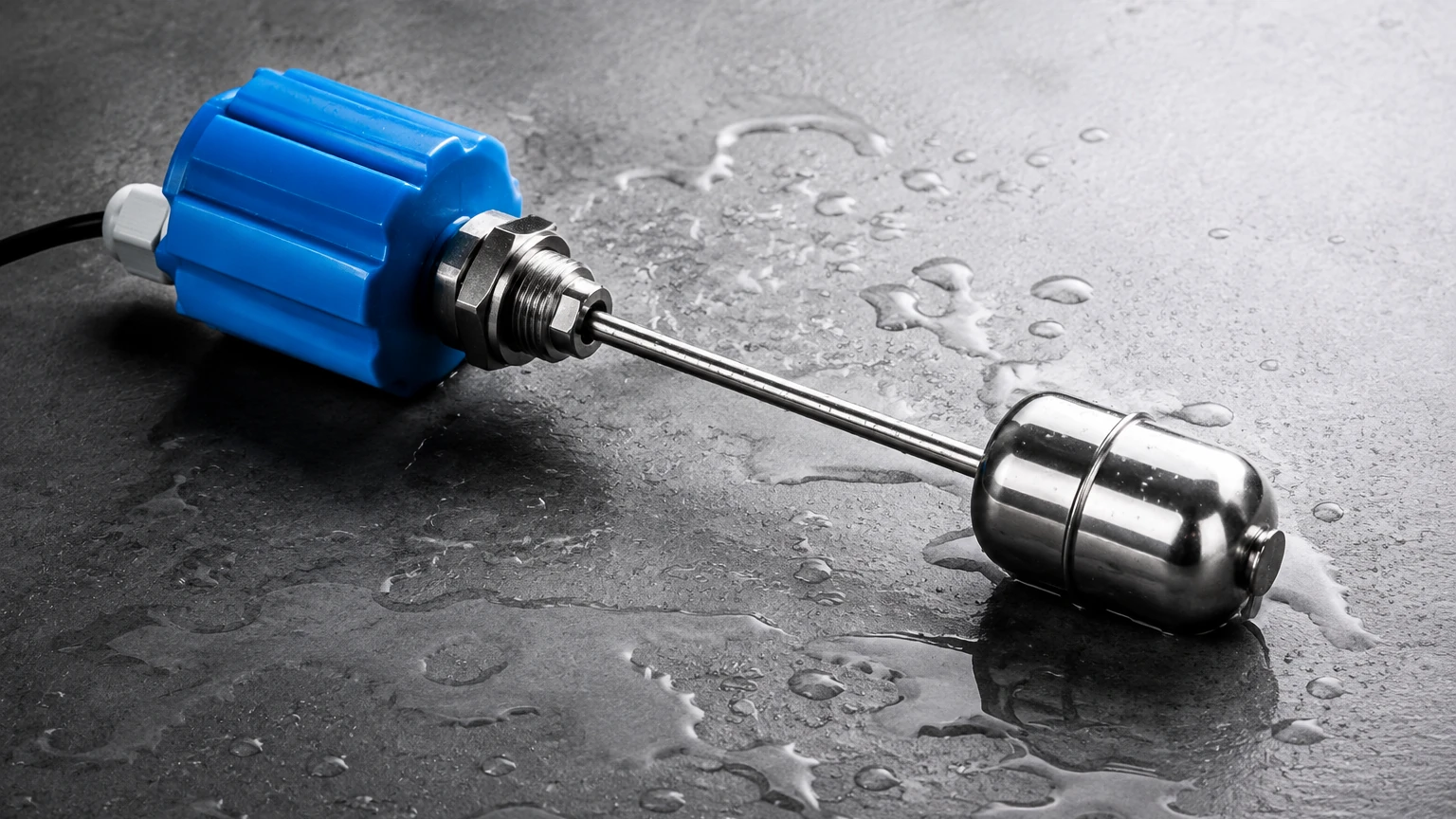
Most modern vertical liquid float switches utilize a hermetically sealed reed switch located inside a stationary stem. The float, which contains a permanent magnet, slides along this stem. When the float reaches the position of the reed switch, the magnetic field causes the reeds to touch (closing the circuit) or separate (opening the circuit). Because the switch contacts are sealed in an inert gas environment, they are protected from oxidation and corrosion, leading to a long operational life.
Microswitch Mechanisms
In larger horizontal switches or cable-suspended float balls, a microswitch is often used. In a horizontal side-mounted switch, the float is attached to a lever arm. As the float rises, the arm pivots and mechanically actuates a microswitch. In cable-suspended versions, a rolling ball or a weighted pendulum inside the float housing triggers the microswitch when the float tilts beyond a certain angle (usually 45 degrees).
Contact Configurations
Float switches are typically defined by their contact state:
* Normally Open (NO): The circuit is open when the float is at its rest position (usually bottom) and closes when the liquid rises.
* Normally Closed (NC): The circuit is closed at the rest position and opens as the liquid rises.
Many industrial float switches are reversible; by removing a retaining clip and flipping the float 180 degrees on the stem, the user can change the switch logic from NO to NC or vice versa.
Key Types of Liquid Float Switches
Industrial applications vary significantly in tank geometry and pressure requirements, necessitating different mechanical designs for level switches.
1. Vertical Multi-Point Float Switches
These consist of a single stem with multiple reed switches positioned at specific heights. A single stem can monitor "Low-Low," "Low," "High," and "High-High" levels. This is highly efficient for tank inventory management as it only requires one process connection (e.g., a single 2-inch NPT or flange) to provide four or more switching points.
2. Side-Mounted (Horizontal) Float Switches
When the top of a tank is inaccessible due to agitators, spray balls, or low overhead clearance, side-mounted switches are used. These are installed through the side wall of the vessel. They are robust and often used in high-pressure hydraulic reservoirs or fuel tanks. They are available in both compact sizes for OEM equipment and heavy-duty flanged versions for industrial processing.
3. Cable-Suspended Float Level Switches
Often referred to as "float balls," these are suspended by their own electrical cable. They are the standard choice for wastewater, sewage sumps, and large open reservoirs. Their design allows them to handle suspended solids and turbulent surfaces better than rigid-stem switches. The switching differential (the distance between the "on" and "off" points) can be adjusted by moving a counterweight along the cable.
Selection Criteria and Technical Specifications
Choosing the wrong material or pressure rating for a liquid float switch can lead to premature failure or safety hazards. Engineers must evaluate the following parameters before procurement.
Material Compatibility
* Stainless Steel (304 or 316L): Ideal for high temperatures (up to 200°C), high pressures (up to 50 bar), and food-grade applications. It is resistant to many organic solvents and oils.
* Polypropylene (PP): A cost-effective choice for general water applications and many acidic or alkaline chemicals. However, it is limited to lower temperatures (typically <80°C).
* PVDF/PTFE: Reserved for highly aggressive chemical environments where even stainless steel would corrode.
Technical Selection Table
| Feature | Stainless Steel (316L) | Polypropylene (PP) | Cable-Suspended (PVC/Neoprene) |
| :— | :— | :— | :— |
| Max Temperature | 200°C | 80°C | 60°C |
| Max Pressure | 50 bar | 5 bar | Atmospheric |
| Min. Specific Gravity | 0.50 | 0.80 | 0.90 |
| Mounting | Top or Side | Top or Side | Suspended |
| Typical Application | Oil, Steam, Food | Water, Acids | Wastewater, Sumps |
Specific Gravity (Density)
For a float to function, its density must be lower than the density of the liquid. Most standard floats are designed for water (SG = 1.0). If you are measuring light oils or hydrocarbons with an SG of 0.7, you must select a float specifically weighted for low-density fluids to ensure it actually floats rather than sinking to the bottom.
Installation and Engineering Best Practices
Proper installation is critical to prevent "chatter" (rapid cycling of the switch) and mechanical damage. For comprehensive technical support and to Review product options and application support, engineers should consult the manufacturer's detailed wiring and mounting diagrams.
Positioning and Turbulence
Float switches should never be installed directly in the path of a tank's fill pipe. The force of the incoming liquid can damage the stem or cause the float to oscillate, triggering false alarms. If turbulence is unavoidable, a stilling well should be used. A stilling well is a pipe (usually 50mm to 100mm in diameter) that surrounds the switch, protecting it from waves and currents while allowing the liquid level inside the pipe to equalize with the tank.
Electrical Protection
Reed switches are sensitive to over-current. While they can trigger a small signal to a PLC, they should not be used to directly power a heavy-duty pump motor. High inductive loads can cause arcing across the reed contacts, welding them shut. Always use an intermediate relay or a motor starter to handle the load, using the float switch only as the control signal.
Orientation
Vertical switches must be installed within 20 to 30 degrees of true vertical to prevent the float from binding on the stem. For horizontal switches, ensure the pivot arm has enough clearance from the tank wall or internal baffles to move through its full range of motion.
Limitations and Common Risks
While highly reliable, the liquid float switch is a mechanical device with moving parts, which introduces specific risks:
1. Coating and Scaling: In liquids that tend to crystallize or leave heavy deposits (like calcium buildup in hard water or sticky resins), the float can become stuck to the stem. Regular inspection and cleaning are required in these environments.
2. Magnetic Interference: Since many float switches rely on internal magnets, the presence of ferrous particles in the liquid can be problematic. Iron filings or magnetic scale can accumulate on the float, increasing its weight and eventually causing it to sink or jam.
3. Viscosity: High-viscosity liquids (like heavy molasses or crude oil) can slow the movement of the float, leading to a delayed response. In such cases, large-diameter floats with higher buoyancy forces are necessary.
4. Mechanical Wear: Over millions of cycles, the mechanical pivot points or the reed switch itself will eventually reach the end of its service life. In safety-critical applications, redundant switches (one for control, one for high-level alarm) are recommended.
Frequently Asked Questions (FAQs)
Q: Can a liquid float switch provide continuous level measurement (e.g., 4-20mA output)?
A: Standard float switches are point-level devices (On/Off). However, "float level transmitters" exist that use a series of closely spaced reed switches and resistors to provide a stepped quasi-continuous output. For true continuous measurement, radar or ultrasonic sensors are usually preferred.
Q: How do I test a float switch without filling the tank?
A: For vertical switches, you can manually slide the float up and down the stem while checking continuity with a multimeter. For side-mounted or cable switches, manually tilt the mechanism to listen for the "click" of the microswitch or verify the electrical state change.
Q: What is the difference between a single-point and a multi-point switch?
A: A single-point switch has one float and one set of contacts. A multi-point switch has a longer stem with multiple floats (or one float triggering multiple switches) to detect several different levels, such as pump start, pump stop, and high-level alarm, using only one tank entry point.
Q: Is it possible to use a float switch in a pressurized vessel?
A: Yes, but you must select a float made of stainless steel or high-strength plastic that can withstand the external pressure without collapsing. Welk offers specialized high-pressure floats rated for up to 50 bar (5 MPa).
Conclusion
The liquid float switch remains a cornerstone of industrial level control due to its simplicity and the definitive nature of its physical operation. By carefully matching the material of construction to the chemical properties of the fluid and adhering to strict installation guidelines regarding turbulence and electrical loads, engineers can ensure years of maintenance-free service. For those seeking to integrate these sensors into modern automation systems, visiting the Main Page of the manufacturer’s site provides access to the latest technical data sheets and configuration tools necessary for precise instrument selection.