How Does a Differential Pressure Transducer Work
How Does a Differential Pressure Transducer Work
Differential pressure (DP) transducers are fundamental components in modern industrial process control. Whether they are monitoring the flow of chemicals through a pipeline or determining the liquid level in a pressurized vessel, these instruments provide the critical data necessary for safety and efficiency. Understanding how does a differential pressure transducer work is essential for engineers and technicians tasked with selecting, installing, and maintaining level measurement systems.
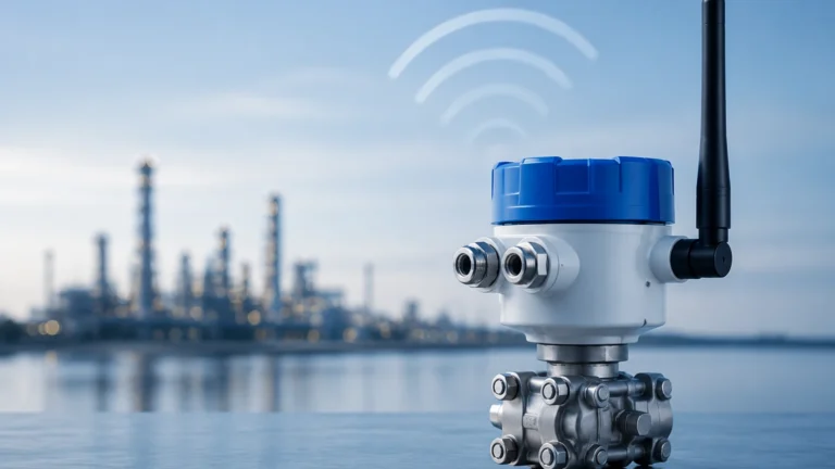
In the context of industrial automation, a differential pressure transducer—often referred to as a DP cell or transmitter—measures the difference between two pressure points. Unlike a standard pressure gauge that measures pressure relative to the atmosphere (gauge pressure) or a vacuum (absolute pressure), the DP transducer is concerned only with the "delta" or the difference between its two input ports.
The Fundamental Physics of Differential Pressure
At its core, a differential pressure transducer operates on a simple mechanical principle: the comparison of two forces. The instrument features two process connections, typically labeled as the "High" (H) side and the "Low" (L) side. It is important to note that these labels refer to the relative pressure applied to the ports, not necessarily the physical height of the installation.
When pressure is applied to both sides, the internal sensing element reacts to the resultant force. If the pressure on the High side is greater than the Low side, the sensing element moves toward the Low side. If they are equal, the element remains in a neutral position. This physical displacement is then converted into an electrical signal.
In liquid level measurement applications, this principle is used to calculate the height of a liquid column based on hydrostatic pressure. According to Pascal's Law, the pressure at the bottom of a liquid column is equal to the height of the column multiplied by the density of the fluid and the constant of gravity ($P = \rho gh$). By measuring the pressure at the bottom of a tank and comparing it to the pressure at the top (in closed systems), the transducer can accurately determine the liquid level regardless of the internal tank pressure.
Internal Mechanics: How the Transducer Converts Force to Signal
To answer the question of how does a differential pressure transducer work at a technical level, we must look inside the housing. Most modern industrial transducers utilize one of two primary sensing technologies: piezoresistive or capacitive.
1. Piezoresistive Sensing
In a piezoresistive transducer, the sensing element consists of a silicon diaphragm with integrated strain gauges. As the differential pressure causes the diaphragm to flex, the electrical resistance of the strain gauges changes. This change is proportional to the amount of deflection. A Wheatstone bridge circuit typically detects this resistance change and converts it into a voltage signal, which is then conditioned into a standard industrial output like 4-20mA or a digital signal via HART or Modbus protocols.
2. Capacitive Sensing
Capacitive DP transducers utilize a central sensing diaphragm positioned between two fixed capacitor plates. The internal chambers are filled with a fill fluid (usually silicone oil) to transmit the process pressure from the isolation diaphragms to the central sensing diaphragm. When a pressure difference occurs, the central diaphragm moves, changing the capacitance between it and the fixed plates. Because capacitance is inversely proportional to the distance between the plates, this technology is highly sensitive and stable over long periods.
Applications in Level Measurement
While DP transducers are versatile, their application in level measurement is one of their most common uses in industries like water treatment and chemical processing. The configuration depends on whether the tank is open or closed.
Open Tank Measurement
In an open-to-atmosphere tank, the Low side of the transducer is vented to the atmosphere. The High side is connected to the bottom of the tank. The transducer measures the hydrostatic head of the liquid. Since the atmospheric pressure acts on both the surface of the liquid and the Low side of the transducer, it cancels out, leaving only the pressure exerted by the liquid column.
Closed Tank Measurement
In pressurized vessels, such as those found in oil and gas or chemical refining, the space above the liquid is filled with gas or steam. This top pressure must be subtracted to find the true liquid level. The High side is connected to the bottom of the tank, and the Low side is connected to the top. This ensures that the transducer only measures the pressure generated by the liquid itself.
* Dry Leg: Used when the gas above the liquid will not condense at ambient temperatures. The pipe connecting the top of the tank to the Low side remains filled with gas.
* Wet Leg: Used when the gas is likely to condense (e.g., steam). The Low-side reference line is intentionally filled with a reference liquid to prevent erratic readings caused by random condensation.
Selection Criteria for Industrial Applications
Choosing the right instrument requires a thorough understanding of the process conditions. The following table outlines the key parameters to evaluate when reviewing options on the Main Page.
| Parameter | Consideration | Why it Matters |
| :— | :— | :— |
| Pressure Range | Minimum and maximum differential | Ensures the sensor is sensitive enough but won't be damaged by overpressure. |
| Static Pressure | Total system pressure | The transducer must withstand high line pressure while measuring small differences. |
| Wetted Materials | 316L SS, Hastelloy, Monel, Tantalum | Must be chemically compatible with the process fluid to prevent corrosion. |
| Accuracy | Percentage of span (e.g., ±0.075%) | Critical for custody transfer or precise chemical dosing. |
| Temperature Limits | Ambient and process temperature | High temperatures may require remote seals or cooling elements. |
| Output Protocol | 4-20mA, HART, Profibus, Modbus | Determines compatibility with the existing PLC/SCADA system. |

Installation and Engineering Best Practices
Even the most accurate DP transducer will fail to provide reliable data if installed incorrectly. Engineering teams should adhere to the following guidelines:
1. Impulse Line Slope: To prevent gas bubbles from being trapped in liquid lines (or liquid from trapping in gas lines), impulse piping should be sloped at least 1:12 (8%).
2. Manifold Valves: Always use a 3-valve or 5-valve manifold. This allows the transducer to be zeroed under static pressure and enables safe removal for calibration without shutting down the process.
3. Mounting Location: For liquid applications, the transducer should ideally be mounted below the process taps to ensure the impulse lines remain full of liquid. For gas applications, mount the transducer above the taps so condensate drains back into the process.
4. Seal Pot Usage: In high-temperature or corrosive applications, use remote diaphragm seals connected via capillary tubes. This protects the sensitive internal electronics from harsh process conditions.
Limitations and Accuracy Considerations
While DP technology is robust, it has inherent limitations that engineers must account for:
* Density Sensitivity: Since DP transducers measure mass-based pressure, any change in the liquid's density (often caused by temperature fluctuations) will result in a level error. If the process temperature varies significantly, temperature compensation must be implemented in the control system.
* Impulse Line Plugging: In applications involving slurries or viscous fluids, the small-diameter impulse lines can become blocked. In these cases, a flush-diaphragm or remote-seal transmitter is preferred.
* Gas Pockets: In liquid level systems, a gas bubble trapped in a "wet" impulse line creates a false pressure offset, leading to inaccurate level readings.
Frequently Asked Questions (FAQ)
Q: Can a differential pressure transducer be used for flow measurement?
A: Yes. By placing a primary flow element (like an orifice plate or Venturi tube) in a pipe, the transducer measures the pressure drop across the restriction. The flow rate is proportional to the square root of the differential pressure.
Q: What is the difference between a pressure transmitter and a pressure transducer?
A: While the terms are often used interchangeably, a "transducer" generally refers to the sensing element that converts pressure to a low-level electrical signal (like millivolts), whereas a "transmitter" includes signal conditioning to provide a standardized industrial output (like 4-20mA).
Q: How often should a DP transducer be calibrated?
A: Most industrial-grade instruments from manufacturers like Welk are highly stable. However, a standard calibration interval is typically 12 to 24 months, depending on the criticality of the process and environmental conditions.
Q: What happens if the High and Low sides are accidentally swapped?
A: Most modern digital transmitters can be reconfigured via software to reverse the reading. Mechanically, the instrument will simply show a negative pressure or an error signal if the Low side pressure exceeds the High side beyond its calibrated range.
Conclusion
Understanding how does a differential pressure transducer work allows engineers to leverage one of the most reliable and cost-effective technologies in the process industry. By accurately interpreting the force exerted by liquid columns and process gases, these instruments ensure that tanks do not overflow and that chemical reactions remain within safe parameters. For those looking to implement these solutions, it is vital to match the transducer's material and technology to the specific rigors of the application. Review product options and application support on our Main Page to find the ideal measurement solution for your facility.
Download How Does a Differential Pressure Transducer Work as a PDF