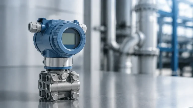
Liquid Flow Transmitter
Liquid Flow Transmitter
In modern industrial automation, the accurate measurement of fluid movement is essential for process efficiency, safety, and inventory management. A liquid flow transmitter is an instrument designed to measure the flow rate of a liquid through a pipeline and convert that physical measurement into a standardized electrical signal, such as 4-20mA, HART, or Modbus. This signal is then transmitted to a control system, such as a PLC or DCS, for monitoring and regulation.
While level measurement focuses on the volume or height of a fluid within a vessel—a field where Welk provides specialized radar and ultrasonic solutions—flow measurement focuses on the dynamic movement of that fluid between points. Understanding the principles, selection criteria, and installation requirements of a liquid flow transmitter is vital for any engineering project involving water treatment, chemical processing, or oil and gas applications.
Measurement Principles and Technologies
To select the correct liquid flow transmitter, one must first understand the physical principles governing different measurement technologies. No single technology is universal; each has specific requirements regarding fluid properties and pipe conditions.
Electromagnetic Flow Transmitters
Electromagnetic transmitters operate based on Faraday’s Law of Electromagnetic Induction. When a conductive liquid flows through a magnetic field generated by the meter, it produces a voltage proportional to its velocity. The formula $E = kBDv$ (where $E$ is voltage, $B$ is magnetic field strength, $D$ is the distance between electrodes, and $v$ is velocity) defines this relationship.
* Requirement: The liquid must have a minimum conductivity, typically $>5$ μS/cm.
* Advantage: No moving parts and no pressure drop.
Ultrasonic Flow Transmitters
These instruments use sound waves to determine flow velocity. There are two primary types: transit-time and Doppler.
* Transit-time: Measures the time difference between ultrasonic pulses traveling with and against the flow. It is ideal for clean liquids.
* Doppler: Measures the frequency shift of sound waves reflecting off particles or bubbles in the liquid. This is better suited for slurries or aerated fluids.
Turbine Flow Transmitters
Turbine meters utilize a multi-bladed rotor suspended in the fluid stream. The fluid pushes the blades, and the rotational speed of the turbine is directly proportional to the flow velocity. Magnetic pickups sense the passing of the blades to generate a frequency signal.
* Requirement: Best for clean, low-viscosity liquids.
* Advantage: High accuracy and fast response times.
Differential Pressure (DP) Transmitters
DP flow measurement relies on Bernoulli’s principle. By placing a restriction in the pipe (like an orifice plate or Venturi tube), a pressure drop is created. The liquid flow transmitter measures the pressure difference before and after the restriction. The flow rate is proportional to the square root of the differential pressure.
Selection Criteria for Industrial Applications
Choosing a liquid flow transmitter requires a thorough evaluation of the process environment. Engineers should confirm the following parameters before procurement:
1. Fluid Characteristics: Is the liquid conductive? What is its viscosity? Does it contain solids or gas bubbles? For example, a magnetic flowmeter will not work with deionized water or hydrocarbons due to low conductivity.
2. Flow Range and Turndown Ratio: The turndown ratio is the range between the maximum and minimum flow the meter can accurately measure. If a process fluctuates significantly, a high turndown ratio is required.
3. Pipe Size and Material: Transmitters are often sized by the nominal diameter (DN) of the pipe. Compatibility between the transmitter liner (e.g., PTFE, PFA, or Neoprene) and the pipe material is crucial for chemical resistance.
4. Accuracy and Repeatability: Critical custody transfer applications require high accuracy (±0.1% to ±0.5%), whereas simple process monitoring might only require ±1.0% to ±2.0%.
5. Environmental Conditions: Consider the ambient temperature, the possibility of submersion (IP68 rating), and whether the area is classified as hazardous (requiring explosion-proof certifications).
Practical Selection and Comparison Table
The following table provides a comparison of common liquid flow transmitter technologies based on standard industrial performance metrics.
| Technology | Typical Accuracy | Conductivity Required | Pressure Drop | Ideal Fluid Type |
| :— | :— | :— | :— | :— |
| Electromagnetic | ±0.5% | Yes (>5μS/cm) | Negligible | Acids, bases, water, slurries |
| Ultrasonic (Transit-Time) | ±1.0% | No | None | Clean water, oils, chemicals |
| Turbine | ±0.25% | No | High | Fuel, solvents, clean water |
| Vortex | ±1.0% | No | Medium | Low-viscosity liquids, steam |
| Differential Pressure | ±1.0% – ±2.0% | No | Moderate | General purpose, high pressure |
Installation Best Practices and Considerations
The performance of a liquid flow transmitter is heavily dependent on how it is installed. Improper installation is the leading cause of measurement error in industrial settings.
Straight Pipe Requirements
Most flow measurement technologies require a fully developed flow profile to be accurate. This means the fluid should be moving in a predictable, non-turbulent manner. To achieve this, manufacturers specify minimum lengths of straight pipe upstream and downstream of the transmitter. A common rule of thumb is "10D Upstream and 5D Downstream," meaning the straight pipe should be 10 times the pipe diameter before the meter and 5 times after it.
Pipe Orientation and Filling
The pipe must be completely full of liquid for the transmitter to provide an accurate reading. For this reason, installing a transmitter on a vertical pipe with upward flow is often preferred, as this ensures the pipe remains full. If installed horizontally, the transmitter should not be placed at the highest point of the piping system, as air pockets can collect there and interfere with the sensors.
Grounding and Interference
For electromagnetic transmitters, proper grounding is essential. The fluid, the transmitter, and the pipe must be at the same electrical potential to prevent stray currents from creating noise in the measurement signal. In plastic or lined pipes, grounding rings are typically required.
Limitations and Operational Risks
While liquid flow transmitters are robust, they are subject to specific operational risks that can lead to failure or inaccuracy:
* Entrained Gas: Small amounts of air or gas bubbles can cause significant errors in electromagnetic and transit-time ultrasonic meters. In such cases, an air eliminator should be installed upstream.
* Cavitation: If the pressure drops below the liquid's vapor pressure, bubbles form and then collapse. This can physically damage the internal components of turbine or vortex meters and cause erratic readings.
* Scaling and Coating: In chemical or wastewater applications, minerals or biological matter can build up on the electrodes or the inner wall of the transmitter. This changes the internal diameter or insulates the electrodes, leading to drift. Regular maintenance and the selection of non-stick liners (like PTFE) can mitigate this risk.
* Viscosity Changes: Technologies like turbine meters are highly sensitive to viscosity. If the process temperature changes significantly, the resulting change in viscosity may require recalibration or a different measurement technology.
Integration with Level Measurement Systems
In comprehensive industrial automation, flow and level measurements are often used in tandem. For example, in a chemical dosing tank, a radar level sensor from Welk can monitor the total volume remaining, while a liquid flow transmitter on the discharge line ensures the precise amount of chemical is being delivered to the process. This "mass balance" approach allows for redundant verification of process data.
By combining reliable level instrumentation with precisely calibrated flow transmitters, plant operators can achieve a higher degree of control. For a broader overview of industrial instrumentation and to explore our full range of level measurement technologies, please visit our Main Page.
Frequently Asked Questions (FAQ)
Q: Can a liquid flow transmitter measure the flow of gases?
A: While some technologies like Vortex or Differential Pressure can measure both, most liquid flow transmitters (especially electromagnetic) are specifically designed for liquids and will not function with gases.
Q: What is the difference between a flow meter and a flow transmitter?
A: A flow meter is the general term for the device that measures flow. A flow transmitter is a specific type of meter that includes an electronic component (the transmitter) capable of sending a standardized signal to a remote control system.
Q: How often should a liquid flow transmitter be calibrated?
A: Calibration frequency depends on the criticality of the application and the environment. Most industrial standards recommend an annual calibration check, though self-diagnostic features in modern HART-enabled transmitters can sometimes extend these intervals.
Q: Does the direction of flow matter during installation?
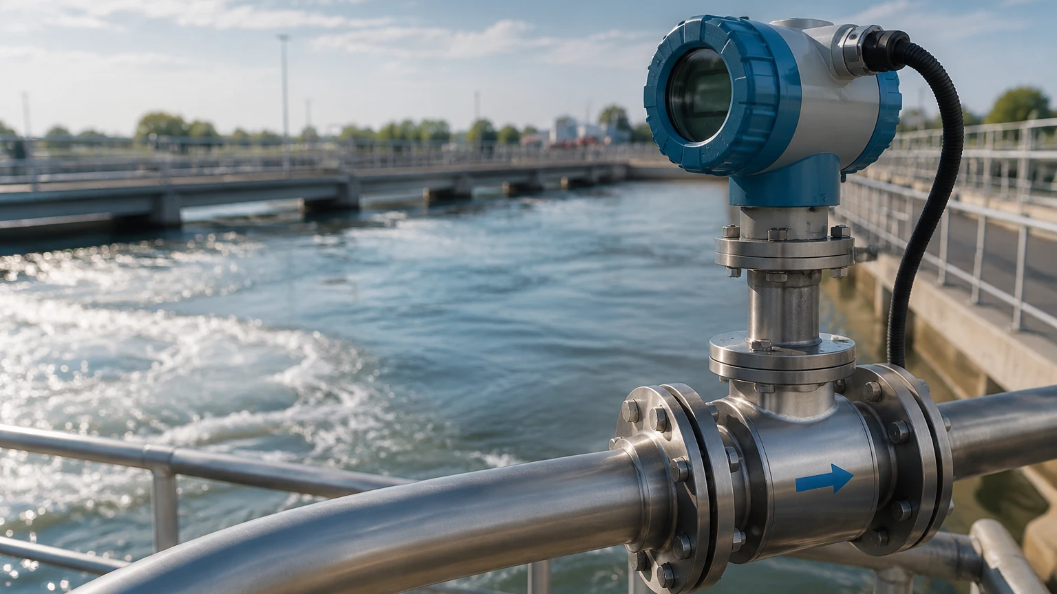
A: Yes. Most transmitters have a flow direction arrow marked on the body. Installing the meter in reverse will result in negative flow readings or errors in the control loop.
Q: Can I install a flow transmitter immediately after a pump?
A: It is not recommended. Pumps create significant turbulence and pressure pulsations. You should follow the manufacturer's straight-run requirements, which usually involve placing the transmitter a significant distance downstream from the pump or using flow straighteners.