Liquid Level Alarm
Liquid Level Alarm
In industrial process control, a liquid level alarm serves as a critical safety and operational threshold indicator. Whether preventing a hazardous chemical overflow or ensuring a pump does not run dry, these systems provide the necessary feedback to automated controllers or human operators. Choosing the correct technology for a liquid level alarm requires a deep understanding of the physical properties of the medium, the vessel geometry, and the environmental conditions of the application.
As a professional manufacturer, Welk emphasizes that an alarm is not merely a switch but a component of a broader safety instrumented system (SIS). This article provides an engineering-focused overview of the technologies used to trigger level alarms, their selection criteria, and practical installation guidance.
Core Measurement Principles for Level Detection
Before selecting a liquid level alarm system, it is essential to understand the underlying physics of how different sensors detect the presence or absence of a liquid. These technologies are generally divided into point level detection and continuous level monitoring with integrated alarm setpoints.
1. Radar Level Measurement (Non-Contact)
Radar level meters utilize Frequency Modulated Continuous Wave (FMCW) or pulsed electromagnetic waves to measure the distance to the liquid surface. High-frequency signals (typically 26GHz or 80GHz) are emitted from the antenna, reflected by the product surface, and received back. The time-of-flight or frequency shift is used to calculate the distance.
* Alarm Application: Radar is ideal for high-accuracy continuous monitoring where high-level or low-level alarms are programmed into the transmitter's software. Because it is non-contact, it is unaffected by changes in density, pressure, or temperature.
2. Ultrasonic Level Sensing
Ultrasonic sensors emit high-frequency sound pulses that bounce off the liquid surface. The sensor measures the time interval between the emission and the return of the echo.
* Alarm Application: These are frequently used in water treatment and open-channel applications. However, they are sensitive to the speed of sound, which varies with air temperature. Most modern Welk ultrasonic sensors include integrated temperature compensation to maintain alarm accuracy. They are generally unsuitable for vacuum applications or high-pressure tanks where the sound medium is inconsistent.
3. Hydrostatic Pressure Transmitters
Hydrostatic sensors measure the pressure exerted by a liquid column at a specific depth. The relationship is defined by the formula: $P = \rho \cdot g \cdot h$ (where $P$ is pressure, $\rho$ is density, $g$ is gravity, and $h$ is height).
* Alarm Application: These are robust solutions for deep wells and vented tanks. A liquid level alarm is triggered when the measured pressure exceeds or falls below a calibrated threshold. It is important to note that if the liquid density changes, the alarm setpoint will shift unless recalibrated.
4. Magnetic Level Gauges and Switches
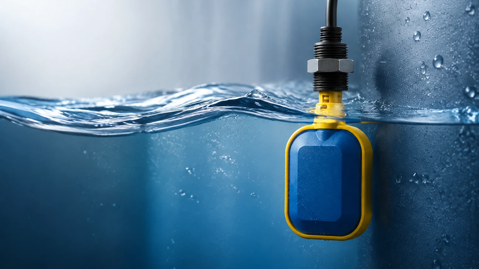
Magnetic level alarms rely on buoyancy. A float containing a permanent magnet moves with the liquid level along a non-magnetic guide tube or bypass chamber. As the float reaches a specific height, the magnetic field actuates a reed switch or a microswitch located outside the process fluid.
* Alarm Application: This is a purely mechanical-to-electrical interface, making it highly reliable for redundant high-level alarms in boilers and oil-water separators.
Technology Comparison and Selection Criteria
Selecting the right liquid level alarm involves balancing cost, accuracy, and maintenance requirements. The following table provides a comparison of common technologies used in industrial environments.
| Technology | Accuracy | Best For | Limitations | Maintenance |
| :— | :— | :— | :— | :— |
| Radar | High (±1mm) | Corrosive chemicals, high temp | Higher initial cost | Very Low |
| Ultrasonic | Moderate (±0.25%) | Wastewater, open sumps | Foam, vapor, vacuum | Low |
| Hydrostatic | Good (±0.1-0.5%) | Deep wells, vented tanks | Density variations | Moderate |
| Magnetic Float | Moderate | High pressure, high temp | Moving parts, fouling | Moderate |
| Tuning Fork | Point Only | Overfill protection | Viscous/sticky fluids | Low |
Key Evaluation Factors
* Chemical Compatibility: Ensure the wetted parts (SS316, PTFE, PP) are resistant to the process medium. For instance, aggressive acids require PTFE-coated radar antennas or plastic ultrasonic bodies.
* Process Conditions: High-pressure environments (above 40 bar / 580 psi) typically require guided wave radar or specialized magnetic gauges. High temperatures (above 150°C / 302°F) may necessitate cooling fins for electronics.
* Vessel Geometry: Internal obstructions like agitators, heating coils, or ladders can interfere with radar and ultrasonic signals. In such cases, a guided wave radar or a bypass chamber for a magnetic float may be required.
For more detailed technical specifications and to explore our full range of instrumentation, you may visit our Main Page for comprehensive product support.
Practical Installation and Configuration Guidelines
Even the most advanced liquid level alarm will fail if installed incorrectly. Engineers should follow these standard practices to ensure reliable performance.
Sensor Placement
1. Avoid the Fill Stream: Never install a level sensor directly under the inlet pipe. The turbulence and falling liquid will cause false alarms or signal loss.
2. Dead Zone (Blocking Distance): Ultrasonic and radar sensors have a "dead zone" near the antenna where measurements are impossible. Ensure the maximum high-level alarm point is below this zone.
3. Wall Interference: Non-contact sensors should be mounted at least 200mm (approx. 8 inches) away from the tank wall to prevent signal reflections from the wall surface or welds.
Wiring and Signal Output
Industrial liquid level alarms typically use one of three output types:
* Relay Output (SPDT/DPDT): A dry contact that opens or closes a circuit to trigger a siren, light, or shut off a pump.
* 4-20mA Current Loop: A continuous signal where specific milliamps (e.g., 20mA for High-High) represent alarm states.
* Digital Protocols: Modbus RTU or HART protocols allow for remote diagnostics and multiple alarm setpoints over a single pair of wires.
Stilling Wells and Bypass Chambers
In tanks with heavy agitation or surface foam, installing the sensor inside a stilling well (a vertical pipe with vent holes) can provide a stable surface for measurement. Similarly, a bypass chamber mounted to the side of the tank allows for maintenance without depressurizing the vessel.
Common Risks and Maintenance Strategies
To maintain the integrity of a liquid level alarm system, plant operators must address common failure modes through proactive maintenance.
1. Fouling and Scaling
In applications involving wastewater or crystallization, material can build up on the sensor face. While radar is relatively resistant to this, ultrasonic sensors and float switches can fail. Regular cleaning intervals should be established based on the severity of the buildup.
2. Turbulence and Foam
Surface foam can absorb ultrasonic pulses, leading to a "Loss of Echo" error. Radar, particularly at higher frequencies, can penetrate some foam, but heavy, dense foam may still require a guided wave radar solution. If an alarm is triggered by turbulence, software damping (averaging the signal over several seconds) can be applied.
3. Redundancy in Critical Applications
For high-consequence scenarios, such as fuel storage or toxic chemical processing, the "1oo2" (one out of two) or "2oo3" voting logic is recommended. This involves using two or three different technologies (e.g., a radar transmitter and a separate tuning fork switch) to ensure that a single sensor failure does not result in a missed alarm.
Frequently Asked Questions (FAQ)
Q: Can a liquid level alarm be used for solids?
A: Yes, but the technology choice changes. Radar and ultrasonic can work for solids, but the angle of repose must be considered. Tuning forks for solids are specifically designed with larger tines to prevent material bridging.
Q: What is the difference between a point level switch and a continuous level transmitter?
A: A point level switch only detects if the liquid has reached a specific height (on/off). A continuous transmitter provides a real-time measurement of the entire range (0-100%) and allows for multiple programmable alarm setpoints.
Q: How often should I test my liquid level alarm?
A: For safety-critical applications, a "proof test" should be conducted annually or as dictated by the Safety Integrity Level (SIL) rating of the loop. This involves physically raising the liquid level or manually moving the float to verify the alarm triggers correctly.
Q: Is it possible to have a wireless liquid level alarm?
A: Yes, many modern systems use LoRaWAN or WirelessHART to transmit level data to a central gateway, which is useful for remote tanks where trenching for cables is cost-prohibitive.
By integrating the correct measurement principle with robust installation practices, industrial facilities can ensure their liquid level alarm systems provide the necessary protection for personnel, equipment, and the environment. For further assistance in selecting a system tailored to your specific process parameters, consult with an applications engineer to review the available technical options.