Liquidline
Liquidline
In the context of industrial process automation and storage, the term "liquidline" refers to the interface or boundary between a liquid medium and the headspace (gas or vapor) above it. Accurately determining the position of this liquidline is fundamental to inventory management, process safety, and efficiency across industries such as water treatment, chemical processing, oil and gas, and food production.
Monitoring the liquidline requires a deep understanding of the physical properties of the medium, the vessel environment, and the specific measurement technology employed. This guide examines the principles of liquid level measurement, selection criteria for various technologies, and practical installation considerations for engineers and plant managers.
Measurement Principles for Liquidline Detection
To effectively track the liquidline, several physical principles are utilized. These are broadly categorized into non-contact and contact measurement methods.
Non-Contact Technologies
Non-contact methods are preferred when the liquid is corrosive, viscous, or when hygiene is a priority, as the sensor does not physically touch the medium.
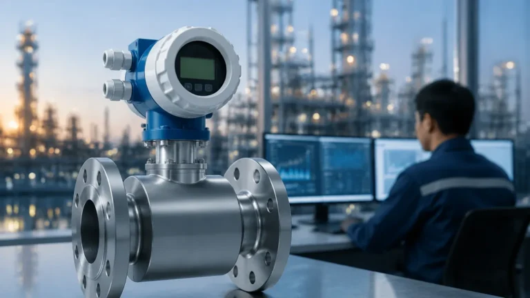
1. Radar Level Measurement (ToF): Radar sensors emit high-frequency electromagnetic waves (typically in the 26GHz or 80GHz range). These waves travel to the liquidline, reflect off the surface, and return to the sensor. The device calculates the distance based on the Time of Flight (ToF). Radar is highly effective because electromagnetic waves are largely unaffected by temperature fluctuations, vacuum, or high pressure.
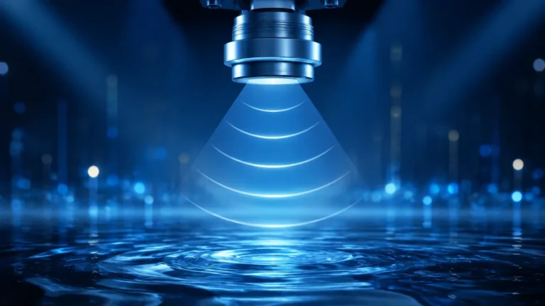
2. Ultrasonic Level Measurement: Similar to radar, ultrasonic sensors use ToF but rely on sound waves. A transducer emits an ultrasonic pulse that bounces off the liquid surface. Because the speed of sound is influenced by air temperature, these sensors usually include integrated temperature compensation. They are cost-effective for open-air applications like water tanks but may struggle in the presence of heavy foam or dust.
Contact Technologies
Contact methods involve a probe or sensor element that is either partially submerged or interacts directly with the liquid surface.
1. Hydrostatic Pressure: This principle relies on the fact that the pressure at the bottom of a vessel is directly proportional to the height of the liquid column above it. By measuring the pressure and knowing the density of the liquid, the liquidline can be calculated using the formula $P = \rho \cdot g \cdot h$. This is a robust method for vented tanks.
2. Magnetic Level Gauges: These utilize a float containing a permanent magnet. As the liquidline rises or falls, the float moves accordingly, actuating a visual indicator or a transmitter mounted outside the chamber. This provides a clear, mechanical indication of the level without requiring power for the visual component.
3. Level Switches: For point-level detection (high or low alarms), switches such as tuning forks or float switches are used. They provide a binary signal when the liquidline reaches a specific threshold, preventing overflows or dry-running of pumps.
Key Evaluation Criteria for Technology Selection
Selecting the correct instrument to monitor the liquidline depends on several technical factors. Engineers must evaluate the following criteria before finalizing a specification:
Media Properties
* Dielectric Constant ($ε_r$): For radar measurement, the reflectivity of the liquidline depends on the dielectric constant. Liquids with low $ε_r$ (like hydrocarbons) reflect less energy than water-based liquids.
* Density: Hydrostatic sensors are highly sensitive to density changes. If the process involves different liquids or varying temperatures that change the density, the measurement will drift unless compensated.
* Viscosity and Coating: High-viscosity liquids can coat contact probes, leading to false readings. In such cases, non-contact radar or ultrasonic sensors are superior.
Vessel Geometry and Environment
* Internal Obstructions: Agitators, ladders, and heating coils can create false echoes for radar and ultrasonic sensors. Modern instruments use "false echo suppression" software to ignore these fixed objects.
* Pressure and Temperature: Extreme conditions (e.g., >100 bar or >250°C) typically require specialized radar or high-pressure magnetic gauges. Hydrostatic sensors must be rated for the specific process temperature to avoid diaphragm damage.
Technical Selection Table
The following table provides a comparison of common technologies used to track the liquidline in industrial settings.
| Technology | Accuracy | Max Range | Media Suitability | Limitations |
| :— | :— | :— | :— | :— |
| 80GHz Radar | ±1 mm | Up to 120m | Corrosive, high temp, foam | Higher initial cost |
| Ultrasonic | ±0.25% of range | Up to 30m | Water, wastewater | Affected by foam, wind, and temp |
| Hydrostatic | ±0.1% to 0.5% | Varies by pressure | Clean liquids, oils | Density must be constant |
| Magnetic Gauge | ±5 mm to 10 mm | Up to 6m (standard) | Clean or dirty liquids | Moving parts subject to wear |
| Tuning Fork | Point Level | N/A | Most liquids | Subject to heavy build-up |
Installation Considerations for Accurate Liquidline Tracking
Even the most advanced sensor will fail if installed incorrectly. To ensure the liquidline is detected accurately, follow these engineering guidelines:
Positioning the Sensor
* Avoid the Center: In cylindrical tanks, do not install radar or ultrasonic sensors in the exact center. This can cause multiple reflections from the tank walls to converge, creating a "focal point" that interferes with the signal.
* Inlet Proximity: Never install a sensor directly above the liquid inlet. The turbulence and splashing from the incoming flow will disturb the liquidline and cause erratic readings.
* Dead Zones (Blocking Distance): Every non-contact sensor has a "dead zone" near the face of the transducer where it cannot measure. Ensure the maximum liquidline level stays below this distance (typically 10 cm to 50 cm depending on the frequency).
Environmental Protection
* Stilling Wells: In applications with heavy surface turbulence or foam, installing the sensor inside a stilling well (a vertical pipe) can provide a calm liquidline for more stable measurements.
* Nozzle Length: For radar sensors, ensure the nozzle height is as short as possible. Long, narrow nozzles can cause internal reflections that mask the actual liquid level near the top of the tank.
Common Risks and Limitations
When managing the liquidline, engineers must be aware of potential failure modes:
1. Vapor and Condensation: While radar penetrates vapor, heavy condensation on an ultrasonic transducer face can block the sound pulse entirely. Some sensors feature a "dripping" design to shed condensate.
2. Foam Interference: Thick, dense foam can absorb radar and ultrasonic signals. In these scenarios, hydrostatic pressure or a magnetic level gauge is often a more reliable choice as they measure the liquid mass or buoyancy rather than the surface reflection.
3. Signal Loss (Blackout): If the liquidline is extremely turbulent or tilted (e.g., in a moving vessel), the reflected signal may not return to the sensor. High-frequency 80GHz radar with a narrow beam angle is best suited to overcome these challenges.
Frequently Asked Questions (FAQs)
Q: How does the dielectric constant affect liquidline detection?
A: In radar technology, the dielectric constant ($ε_r$) determines how much energy is reflected. Water has a high $ε_r$ (~80) and is easy to detect. Oils have a low $ε_r$ (~2), meaning more energy passes through the surface and less returns to the sensor, requiring a more sensitive instrument.
Q: Can I use a hydrostatic sensor in a pressurized tank?
A: Yes, but you must use a differential pressure (DP) transmitter. One sensor measures the pressure at the bottom (liquid + gas headspace), and the other measures the gas headspace pressure only. The system subtracts the headspace pressure to find the true hydrostatic head of the liquidline.
Q: What is the benefit of 80GHz radar over 26GHz radar?
A: 80GHz radar has a much narrower beam angle. This allows it to avoid internal obstructions like agitators and makes it easier to install in small nozzles or narrow tanks without interference from the walls.
Conclusion and Next Steps
Maintaining a precise view of the liquidline is essential for operational safety and process optimization. Whether utilizing non-contact radar for aggressive chemicals or hydrostatic transmitters for water reservoirs, the choice of technology must be driven by the specific physical properties of the application. For those seeking detailed technical specifications and product comparisons to find the right fit for their facility, it is advisable to Review product options and application support at the Main Page to ensure all environmental variables are accounted for before procurement.
Before proceeding with an installation, confirm the following with your technical team:
* The exact chemical composition and density of the liquid.
* The maximum and minimum operating temperatures and pressures.
* The presence of any agitators, foam, or steam within the vessel.
* The required accuracy for inventory or process control purposes.