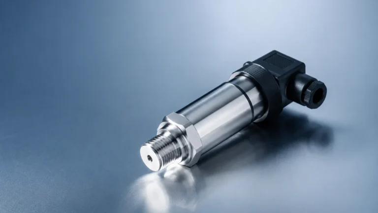
Ultrasonic Water Sensor
Ultrasonic Water Sensor
In the landscape of industrial process control and water management, the ultrasonic water sensor has established itself as a cornerstone technology for non-contact level measurement. These instruments provide a reliable, cost-effective, and low-maintenance solution for monitoring fluid levels in everything from municipal wastewater treatment plants to chemical storage tanks. As a professional manufacturer, Welk specializes in providing high-precision level measurement instruments, ensuring that engineers and facility managers can access accurate data for critical decision-making.
Understanding the technical nuances of these sensors—from their underlying physics to specific installation requirements—is essential for ensuring long-term system reliability. This guide provides a comprehensive technical overview of ultrasonic technology, selection criteria, and practical application strategies for industrial environments.
Measurement Principle: The Physics of Sound
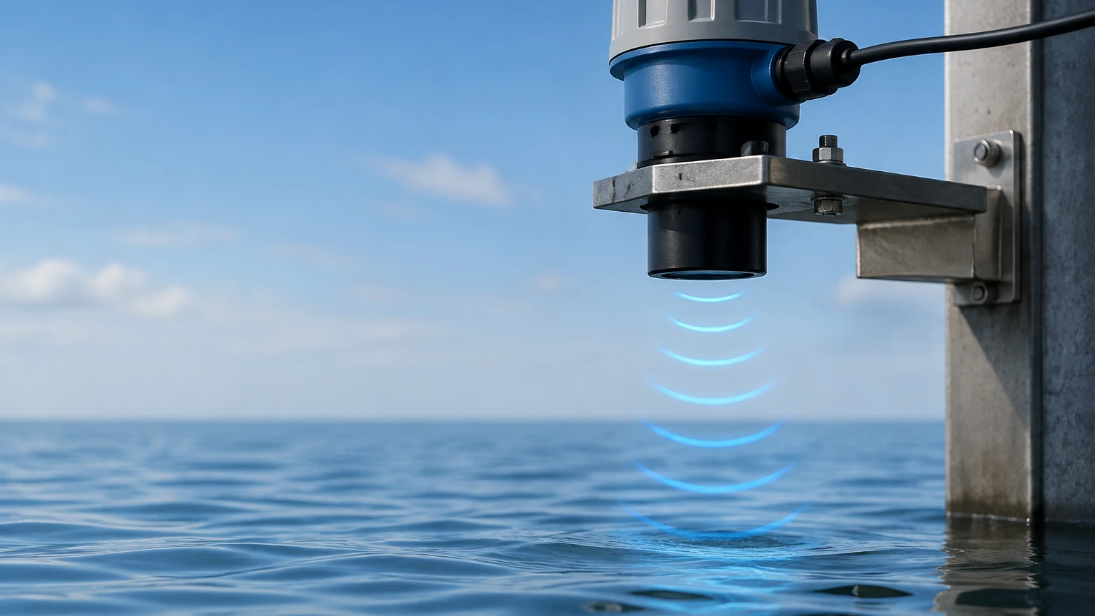
An ultrasonic water sensor operates on the "Time-of-Flight" (ToF) principle. The device contains a piezoelectric crystal that acts as both a transmitter and a receiver. When energized, the crystal vibrates at a high frequency, typically between 20 kHz and 200 kHz, emitting a pulse of ultrasonic sound waves toward the water surface.
The Time-of-Flight Calculation
Once the sound pulse is emitted, it travels through the air, hits the surface of the water, and reflects back to the sensor. The sensor’s internal electronics measure the time interval between the emission of the pulse and the reception of the echo. The distance to the water surface is calculated using the following formula:
D = (c × t) / 2
Where:
* D is the distance from the sensor face to the water surface.
* c is the speed of sound in air (approximately 344 m/s at 20°C).
* t is the total time elapsed for the round trip.
Since the height of the tank or the depth of the channel (H) is a known constant, the actual water level (L) is determined by subtracting the measured distance (D) from the total height (H): L = H – D.
Temperature Compensation
The speed of sound is not a fixed constant; it varies significantly with air temperature. For every degree Celsius change, the speed of sound alters by approximately 0.6 m/s. To maintain accuracy, high-quality ultrasonic water sensors, such as those found on the Welk Main Page, incorporate an integrated temperature sensor. This allows the onboard microprocessor to perform real-time compensation, ensuring that fluctuations in ambient temperature do not result in measurement drift.
Key Advantages in Industrial Applications
Ultrasonic technology is preferred in many B2B sectors due to its non-contact nature. Unlike hydrostatic or float-based sensors, the ultrasonic transducer never touches the liquid. This offers several distinct advantages:
1. Reduced Maintenance: Without moving parts or physical contact with potentially corrosive or fouling liquids, the risk of mechanical failure or sensor degradation is minimized.
2. Versatility: These sensors can measure both liquids and solids (though water is the primary medium) and are effective in open channels, sumps, and closed tanks.
3. Chemical Resistance: Transducer faces can be constructed from PVDF (Polyvinylidene fluoride) or PTFE (Teflon), making them resistant to aggressive chemicals and acids common in water treatment.
Selection Criteria for Ultrasonic Water Sensors
Choosing the right sensor requires an analysis of the specific process environment. Engineers should consult the following table to align sensor specifications with application requirements.
Practical Selection Table
| Feature | Requirement | Consideration |
| :— | :— | :— |
| Measurement Range | 0.1m to 30m | Choose a range that exceeds the maximum depth by at least 20%. |
| Output Signal | 4-20mA, RS485, HART | 4-20mA is standard for PLCs; RS485/Modbus is ideal for digital networking. |
| Beam Angle | 5° to 12° | Narrower beam angles are better for narrow tanks to avoid wall interference. |
| Operating Pressure | Atmospheric | Ultrasonic sensors are generally not suitable for high-pressure vessels. |
| Ingress Protection | IP66, IP67, IP68 | IP68 is required for sensors subject to periodic submersion or heavy spray. |
| Power Supply | 24V DC or 220V AC | 24V DC (2-wire or 3-wire) is the industrial standard for control loops. |
Installation Considerations and Best Practices
Proper installation is the most critical factor in the performance of an ultrasonic water sensor. Even the most advanced instrument will fail to provide accurate data if positioned incorrectly.
1. The Dead Zone (Blocking Distance)
Every ultrasonic sensor has a "dead zone" directly beneath the transducer face, typically ranging from 0.1m to 0.6m depending on the frequency. In this zone, the sensor cannot process the returning echo because the crystal is still vibrating from the transmission.
* Guideline: Ensure the maximum water level never reaches the sensor's dead zone. If the tank might overfill, mount the sensor on a stand-off pipe or a higher bracket.
2. Beam Angle and Obstructions
The ultrasonic pulse spreads out in a cone shape. Any physical obstruction within this cone—such as ladders, pipes, or agitators—will create a "false echo."
* Guideline: The sensor should be mounted at a distance from the wall that is at least 10% of the total height. If obstructions are unavoidable, select a sensor with "False Echo Suppression" software that can be programmed to ignore static reflections.
3. Mounting Orientation
The transducer must be mounted perfectly perpendicular to the water surface. If the sensor is tilted, the sound waves will reflect away from the receiver, resulting in a "Loss of Echo" (LOE) error.
* Guideline: Use a spirit level during installation. For outdoor applications in flumes or weirs, ensure the mounting bracket is rigid enough to withstand wind vibration.
Limitations and Environmental Challenges
While highly versatile, ultrasonic water sensors are not universal solutions. Certain environmental factors can interfere with the acoustic signal:
* Surface Foam: Heavy, thick foam acts as an acoustic absorber. The sound pulse enters the foam and is dissipated rather than reflected, leading to signal loss. If foam is constant, a radar level meter or a hydrostatic transmitter may be more appropriate.
* Heavy Vapor and Dust: While light moisture is compensated for, extremely dense steam or dust can change the medium's density through which the sound travels, affecting the speed of sound beyond what temperature compensation can fix.
* Vacuum Conditions: Sound requires a medium (air or gas) to travel. Ultrasonic sensors cannot function in a vacuum.
* Turbulence: Extreme surface turbulence can scatter the echo. This can often be mitigated by using a stilling well—a vertical pipe that dampens the surface movement while allowing the water level to rise and fall naturally.
Frequently Asked Questions (FAQ)
Q: Can ultrasonic sensors measure water level through a closed plastic tank lid?
A: No. The sound waves cannot penetrate solid materials like plastic or metal lids. The sensor must have a clear path to the liquid surface, usually through a threaded port or a flange mounting.
Q: How does wind affect outdoor ultrasonic measurements?
A: Strong winds can "blow" the sound wave away, especially over long distances (e.g., 10+ meters). For outdoor open-channel flow measurement, it is recommended to use a sensor with a higher power output or a protective sun/wind shield.
Q: What is the difference between an integrated and a split-type sensor?
A: An integrated sensor has the transducer and the display/electronics in one housing. A split-type sensor separates the transducer from the controller (connected by a cable). Split-type models are ideal when the measurement point is difficult to access or is in a hazardous area, allowing the display to be mounted at eye level or in a control room.
Q: How often do these sensors need calibration?
A: Under stable environmental conditions, ultrasonic sensors are very stable. However, an annual check against a manual dip-tape measurement is standard industrial practice to ensure the temperature compensation and electronics remain within specified accuracy limits (typically ±0.25% to ±0.5% of range).
Comparison: Ultrasonic vs. Other Technologies
| Technology | Contact Type | Cost | Best Use Case |
| :— | :— | :— | :— |
| Ultrasonic | Non-contact | Moderate | Open channels, sumps, standard chemical tanks. |
| Radar (60GHz/80GHz) | Non-contact | Higher | High-precision, tanks with steam, dust, or light foam. |
| Hydrostatic | Contact | Lower | Deep wells, boreholes, pressurized tanks. |
| Magnetic Gauge | Contact | Moderate | High-pressure, high-temperature boilers. |
Conclusion
The ultrasonic water sensor remains a premier choice for industrial B2B applications due to its balance of accuracy, ease of installation, and low total cost of ownership. By understanding the importance of the dead zone, beam angle, and temperature compensation, engineering teams can implement robust level monitoring systems that withstand the rigors of industrial use. For those seeking specific product configurations or technical support for complex installations, reviewing the various options available on the Welk Main Page is a recommended next step in the procurement process.