Machine Direction Control for Pulp
Machine Direction Control for Pulp
In the pulp and paper industry, Machine Direction (MD) control refers to the systematic regulation of process variables along the longitudinal path of the production line. Unlike Cross-Direction (CD) control, which manages uniformity across the width of the sheet, MD control focuses on maintaining consistency over time as the pulp slurry moves through the machine. Achieving stable machine direction control for pulp is fundamental to ensuring the final product meets specifications for basis weight, moisture content, and thickness.
At the heart of effective MD control lies the precise management of fluid dynamics and material consistency. For process engineers, this begins with accurate level measurement in headboxes, machine chests, and storage tanks. Without reliable level data, the control loops responsible for fiber flow and chemical dosing cannot function correctly, leading to variance in the finished product. This guide explores the measurement principles, technology selection, and installation strategies required to optimize MD control in modern pulp processing.
Measurement Principles for MD Control
To maintain stability in the machine direction, the control system must account for the volume and pressure of the pulp stock at various stages. Level measurement instruments provide the primary feedback signal for these loops. Understanding the underlying physics of these sensors is critical before selecting a solution for a specific application.
Radar Level Measurement (FMCW)
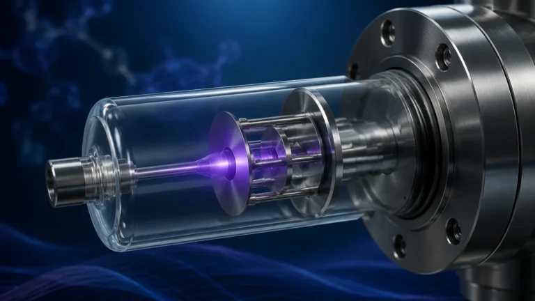
Frequency Modulated Continuous Wave (FMCW) radar is the preferred technology for high-precision MD control. The sensor emits a continuous signal with a changing frequency. The reflection from the pulp surface is received, and the frequency difference between the emitted and received signal is used to calculate the distance. Because radar does not require a physical medium for transmission, it is unaffected by the steam, high temperatures, and vacuum conditions often found in pulp headboxes.
Hydrostatic Pressure Measurement
Hydrostatic transmitters measure the pressure exerted by the liquid column above the sensor. In pulp applications, this is calculated using the formula $P = \rho gh$, where $P$ is pressure, $\rho$ is the density of the pulp slurry, $g$ is gravity, and $h$ is the height of the liquid. While highly reliable for open tanks, hydrostatic measurement is sensitive to changes in stock consistency (density). Therefore, it is often used in applications where the pulp density is strictly controlled or where the sensor can be compensated via the control system.
Ultrasonic Measurement
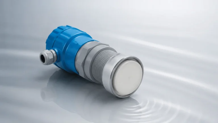
Ultrasonic sensors utilize sound waves that bounce off the surface of the material. The time-of-flight (ToF) determines the level. While cost-effective, ultrasonic sensors face limitations in pulp mills due to the presence of foam, heavy vapors, and acoustic noise from machinery, which can attenuate or scatter the signal. They are generally reserved for water treatment or secondary chemical storage rather than the primary pulp line.
The Relationship Between Level Stability and MD Control
Machine direction control for pulp relies on a "cascade" control strategy. The Quality Control System (QCS) monitors the final sheet properties and sends setpoint adjustments to the Distributed Control System (DCS). The DCS, in turn, manages the flow of stock and the level of the headbox.
If the level in the machine chest or headbox fluctuates, the total head (pressure) at the slice changes. This variation directly impacts the velocity of the pulp jet, leading to fluctuations in basis weight. By implementing high-accuracy industrial instruments from specialists like Welk, mills can reduce level variance to within ±1mm (0.04 inches), providing the stable foundation necessary for the MD control algorithms to minimize fiber waste and energy consumption.
Practical Selection Table for Pulp Mill Applications
Choosing the right technology depends on the specific demands of the process stage. The following table provides a comparison based on typical pulp mill environments.
| Application | Recommended Technology | Accuracy | Key Advantage | Limitations |
| :— | :— | :— | :— | :— |
| Pressurized Headbox | 80GHz Radar | ±1 mm | Unaffected by pressure/steam | Higher initial cost |
| Machine Chest | Hydrostatic (Flush) | ±0.1% FS | Robust, handles agitation | Sensitive to density shifts |
| Bleach Towers | Non-contact Radar | ±2 mm | Corrosion resistance | Requires clear signal path |
| Chemical Storage | Ultrasonic | ±5 mm | Cost-effective | Impacted by foam and vapor |
| Liquor Tanks | Magnetic Level Gauge | Visual + Output | Redundant safety | Mechanical moving parts |
Installation Considerations for Pulp Environments
Proper installation is as critical as technology selection. In the context of machine direction control for pulp, the following factors must be addressed to ensure signal integrity:
1. Nozzle Geometry: For radar installations, the nozzle height should be kept to a minimum to prevent internal reflections (ringing). If a long nozzle is necessary, a larger diameter is required to maintain a clear "cone" for the signal.
2. Agitation Management: Pulp chests are often equipped with heavy-duty agitators. Level sensors should be positioned in areas with minimal surface turbulence or installed within a stilling well (bypass pipe) to provide a stable surface for measurement.
3. Steam and Condensation: In the wet end of the machine, condensation can form on sensor faces. Selecting instruments with PTFE-coated antennas or integrated air-purge systems prevents droplets from interfering with the measurement.
4. Mounting Position: Sensors should never be mounted directly above the pulp inlet. The falling stream of material will create false echoes and physical interference, leading to erratic MD control signals.

Common Risks and Limitations
While modern instrumentation is highly advanced, certain environmental factors in pulp mills can limit performance:
* Consistency Variations: Hydrostatic sensors assume a constant density. If the pulp consistency fluctuates from 3% to 4%, a hydrostatic sensor will report a level change even if the physical height remains constant. This can lead to incorrect MD control actions.
* Foam Accumulation: Heavy foam on the surface of a tank can absorb ultrasonic signals or cause a "false top" for radar. In high-foam applications, high-frequency (80GHz) radar with advanced signal processing is required to penetrate the foam layer and reach the true liquid surface.
* Build-up and Scaling: Pulp fibers and chemicals can build up on the diaphragm of hydrostatic sensors or the lens of a radar. Flush-mounted diaphragms and non-contact sensors are the primary defenses against this risk.
Frequently Asked Questions (FAQs)
Q: How does headbox level accuracy affect basis weight in MD control?
A: The headbox level (or total head) determines the speed at which the pulp jet hits the forming wire. A 1% error in level measurement can translate to a significant variance in basis weight, as the jet-to-wire speed ratio is a critical parameter for sheet formation.
Q: Can I use a single sensor for both level and density?
A: Not directly. However, by using two hydrostatic sensors at a fixed vertical distance, the system can calculate the real-time density of the pulp, which allows for more accurate level compensation and improved MD control.
Q: Why is 80GHz radar becoming the standard for pulp mills?
A: The higher frequency allows for a narrower beam angle (typically 3 to 6 degrees). This makes it easier to avoid internal tank obstructions like baffles, ladders, and agitators, providing a much cleaner signal for the DCS.
Q: How often should level sensors in the pulp line be calibrated?
A: For critical MD control points, an annual calibration check is recommended. However, non-contact radar sensors often require significantly less maintenance than contact-based hydrostatic sensors because they are not subject to wear or coating.
Conclusion
Optimizing machine direction control for pulp is a multi-faceted challenge that requires a deep understanding of both fluid dynamics and instrumentation. By selecting level measurement technologies that can withstand the harsh, humid, and turbulent environment of a pulp mill, engineers can provide the precise data needed for sophisticated control loops. Whether utilizing the precision of 80GHz radar or the rugged reliability of hydrostatic transmitters, the goal remains the same: achieving a stable, high-quality output that minimizes waste and maximizes production efficiency. For those seeking to upgrade their process capabilities, exploring the full range of Main Page solutions is the first step toward superior machine direction stability.